Ping-pong ball (ice cube tray) neopixel display
A super-low-res neopixel display
A super-low-res neopixel display
To make the experience fit your profile, pick a username and tell us what interests you.
We found and based on your interests.
My original construction method wasn't ideal and I don't recommend it. Stitching to a fabric backing was flawed because that moves and sags. The trays didn't remain well-spaced and they didn't stay stuck in place.
So this week I took it all apart. Well down to the soldered-together neopixel strips. What I effectively did there was to create strips of pixels in a time-consuming and expensive way, but with the pixels at exactly the right pitch for the cells in the trays.
For the 'mark 2' I drilled little holes in the trays and used twists of thin wire (white outer) to 'stitch' the trays together. This worked a treat.
Hurray for hot-glue. I used the stuff to fasten the strips of pixels to the backs of the trays. I don't know how easy this would be to remove, but we'll worry about that when the time comes. In the above picture, you can see more easily how the power and ground take the shorter snaking route, while the data line zig zags, which makes programming a bit easier.
I've done some work on my little control board. I'd made a little prototype board with sockets for a pico and various useful things connected to it like a button, a reset button, a pot. This week I took this 7-segment 3-digit display and wrote a little 'library' for the pico in my preferred language, plain C, and added that to the control board.
(Yes, this little board is from a Gotek. There are a million of these floating around in the world because everyone gets one with a Gotek and then changes it for an oled display.)
I've started to work on one master program for the pico which will include all the little demos and utilities I might want to run on it. The button allows me to cycle these, and the display shows the number. (a bit useless, because you can see which demo is running most of the time.)
The pot adjusts the brightness of the display. I might try using some kind of daylight sensor to auto-adjust that.
The video below shows me flicking through three of the demos that I have installed already. A spinning earth (which just demonstrates that I can convert pngs into 12x12 animation frames), an audio-sampler with FFT and bar display, and the plasma demo I've shown previously.
In the last log I'd completed a 12 x 6 display and had that running. I've now completed 12 x 12 pixels in exactly the same way, although things became quicker and neater the more I did.
Before the reveal I'll note some of the things that I've learned.
The point of this is that I can run any game / demo / utility I care to code. Programming is the part that I enjoy the most, so I'll be able to enjoy working on all sorts of ideas. The plasma demo above is one. The music visualiser below is another that I've been working on. (The reason it's currently showing a lot in the bass is because the little mic is between the speakers, if you put your head there, it sounds very boomy.)
So here we are two weeks later. Each module of 2 x 6 has taken me an evening to put together. (Well, 1-2 hours but each one is getting quicker and neater). As you have seen in the first part, I went for a construction that's cheap on parts but big on time, which is OK because this is very much a hobby project.
Here's the point where I had six modules done (but not wired together). I was keen to connect them and make sure they worked before going any further. This meant deciding how to fasten them together and how I wanted to mount them on the wall. I went for stitching them onto something flexible rather than something rigid like a piece of board, so that the whole thing will be lighter and roll up for storage. I didn't have a bedsheet that I wanted to sacrifice but did have plenty of old towels, so used one of those. I cut and hemmed it to the right size (21" wide) and stitched each of the modules onto it. The ice-cube tray is just placed in position in the photo
So onto the ice-cube trays. Fortunately the store still had some more (They're on offer and are not sold out yet) so I picked up another half dozen. That means I have enough to build my 12x12 display as originally planned. (I've since thought about extending this to 12x18, so I'll see whether they have another half dozen next time I visit.)
They have a rim/lip which needs trimming off to allow the trays to butt together with the bubbles at the right pitch. The little circular saw blade for the Dremel made very short work of those:
... and if any more material needed taking off, and to straighten out any unevenness, 40-grit works very quickly.
I also had to buy more pixels. When I was first inspired to do this I was thinking 8x8 and so I only bought 70.
I bought another 100 for about £30.
These pixels are amazing. For the uninitiated, each 'LED' is actually three LEDs, in this case a red, a green and a blue one, plus a little controller chip. You send it a small amount of data and the controller will manage the three LEDs to make the colour you want, and will maintain that colour as long as you keep supplying power. Each pixel has a single data line in and out and it does a very clever trick that means that you can daisy-chain as many of these as you like.
They're sometimes called 'addressable' but I don't think that's accurate. You can't just send data to a specific pixel, you have to send the data for all of the pixels up to and including the one that you want to change.
Here's a close up. Under the circular lens (which is less than 5mm diameter) you can just about see three darker shapes which I think are the LEDs. The 'squashed bug' in the middle is the controller chip. All of this is within a little square package, and I'm buying these particular ones already mounted on a small circular PCB containing some supporting passives as well as giving you some very convenient solder pads on the back. They arrive scored so that you can snap them off individually or leave them in groups.
Now onto the software side. I have a lot of ideas for things to run on this display, but I wanted a demo for testing that was a little more impressive than the chasing lights I presented in the last project log.
I spent a little time with a Pico and a compact 8x8 matrix and managed to get a 'plasma' demo running. Nice!
Today I made the final connections on my work-in-progress display and powered it on. Predictably, not all lights lit, and some were a bit intermittent. The latter problem was a whisker of wire intermittently shorting out two pads on the back of one of the pixels. The other problem (after some checking and re-checking my connections) was a software problem. Although I'd made my plasma code configurable, I'd been developing it using an 8x8 matrix and forgot to reconfigure for 6x12, and so only 64 of my lights lit. D'oh! That was easily fixed.
I'm thrilled with this. It looks...
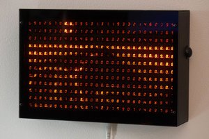
Read more »I was blown away when I saw this display at Liverpool maker festival a couple of years ago.
It was made of ping-pong balls, I can't remember whether they were whole or halved, but the actual construction is one of the barriers that has kept this project from getting off the ground.
However, in my supermarket this week I found these ice-cube trays.
They were on sale at £2.50 for two. I think they'd be terrible for their intended use because they're made of a rigid plastic, so I can't see how you'd pop out the 'cubes' (more like hemispheres). But they do seem absolutely perfect for my purposes! I love the shape of each bubble, they're spherical but with facets. They're a tiny bit smaller than a ping-pong ball and each tray of 12 is perfectly-spaced. The translucency seems just about perfect.
These trays led to the idea of making this modular. I could make a 12 x 12 display, for example, but later add more to make a landscape or portrait display.
This first part isn't so much difficult as tedious. I toyed around with using strips of stripboard, three tracks wide, to construct sticks of 6 neopixels. Designing a custom pcb also crossed my mind.
But for this first test I simply used ribbon cable.
I marked out the layout on a piece of paper and blu-tacked the pixels into place before wiring them. Each 'stick' of 6 has header pins at each end.
(Apologies for the total lack of colour-coding.)
I then cut a piece of card to size, wrapped in white paper. I used foam pads to stick each pixel to this backplate and used white tape, more to disguise the coloured wires than anything else.
Note that I've zig-zagged the connection between these rows. This will make coding just a bit easier but I'm not sure about the final configuration yet.
I trimmed the lip off the tray, so that modules will butt together with the bubbles at roughly the right spacing.
And wow! If these were designed for this purpose, they couldn't have been designed better.
Here's a quick video of a simple animation.
It took quite a while to make this first module. I'm sure the rest will be a little quicker, but I've still got a lot of work to do to complete 11 more. (I've also got my fingers crossed that the store will have 6 more the next time I visit because I only picked up half a dozen initially.)
Create an account to leave a comment. Already have an account? Log In.
Become a member to follow this project and never miss any updates

 Aaron
Aaron
 monte
monte
 Chris Combs