Long time no see eh?
I could give you the whole spiel about my exams getting in the way etc. but between me and you, I am simply just a pathological procrastinator.
JLCPCB Order
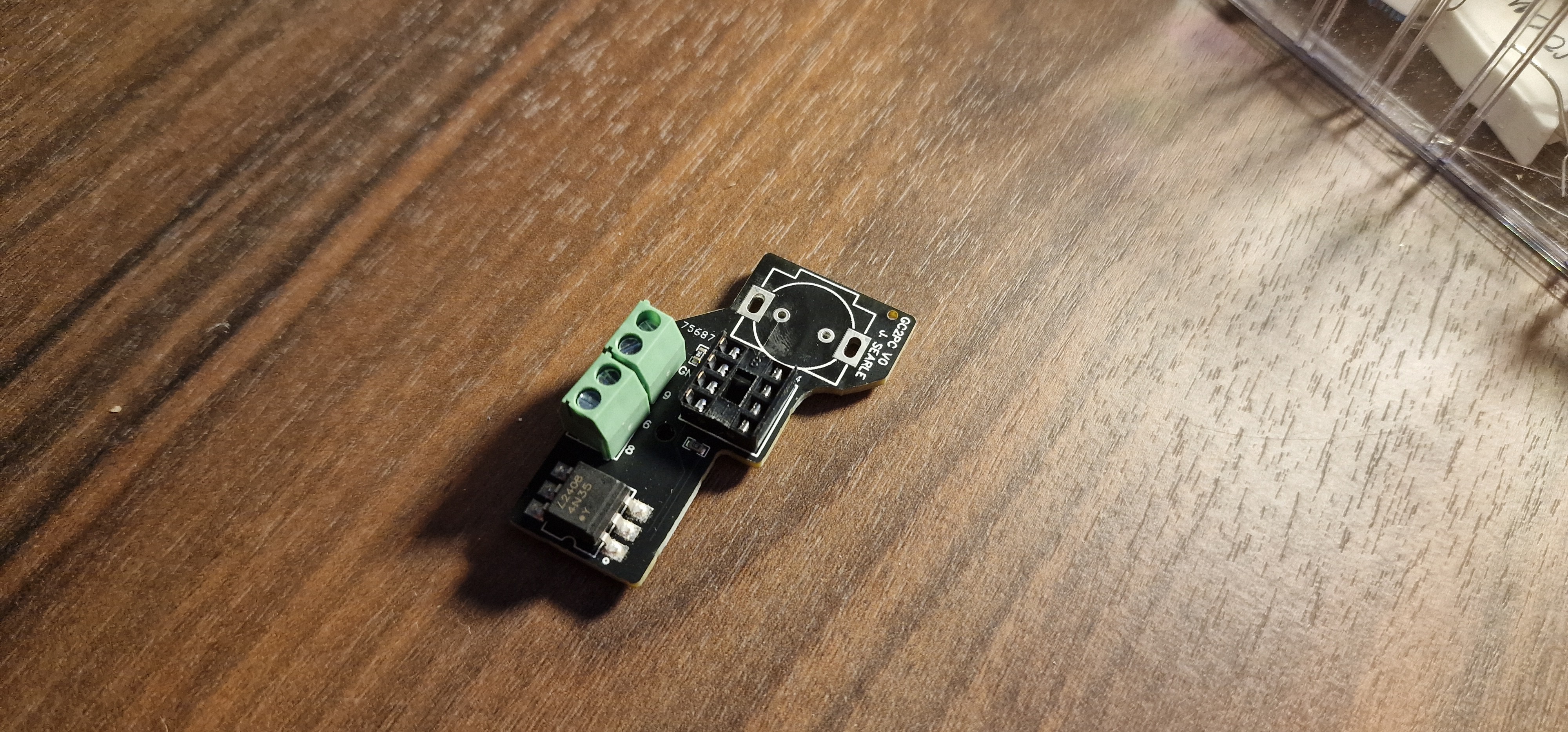
Let's get cracking with where we left off. Firstly, PCB V0 arrived from JLCPCB:

And, I have to say, I was very impressed. I wasn't paid by JLCPCB to say this, but the quality was fantastic. 5 boards arrived pre-assembled and the total cost including shipping was just £24.08 (That's $30.50 for you yanks across the pond) and it only took 10 days.
Despite this, these boards were absolutely useless to me. So I guess they'll look pretty in my box of random electronic components for a few years until I decide to make art out of them or salvage some components.
PCBWay Sponsorship
Whilst pondering over the limited funds in my bank account, I decided to check out PCBWay's sponsorship program. I figured there would be no harm in submitting an application (Here is the post in case you were interested) in the hopes that I could get some support from them to fulfil this project.
Shortly after being accepted for sponsorship, Liam independently slid into my DM's and asked if I would be interested in collaborating with PCBWay on this. He provided my account with the funds to ensure all of my V1.1 boards could be assembled in house rather than just one or two. This would have come to a total of £48.17 ($61.01).
Over the next 19 days I obsessively checked my order status until the boards arrived in my hands. I will admit, I was slightly addicted to the thrill of seeing it move through each stage of production. And don't get me started on the excitement I felt when they even sent me a photo of one of the boards to make sure everything was up to standard before shipping!
Throughout the process, the engineers had a few questions which, instead of simply assuming the answer to, they pinged my way. I was surprised and impressed with this level of service given how quickly the turnaround was.
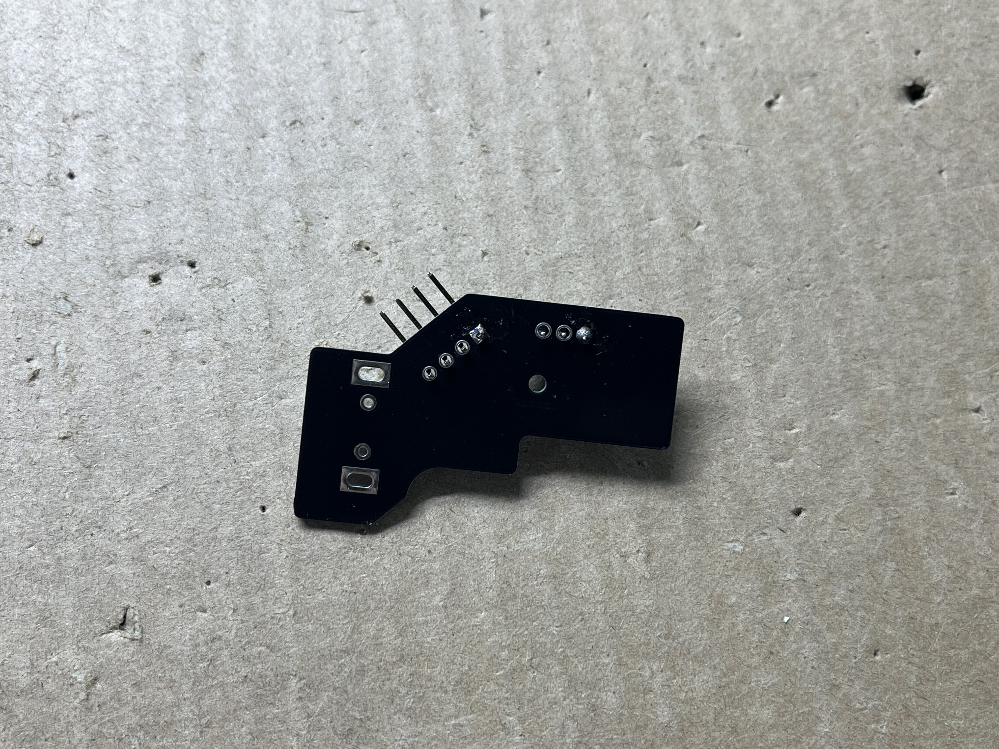
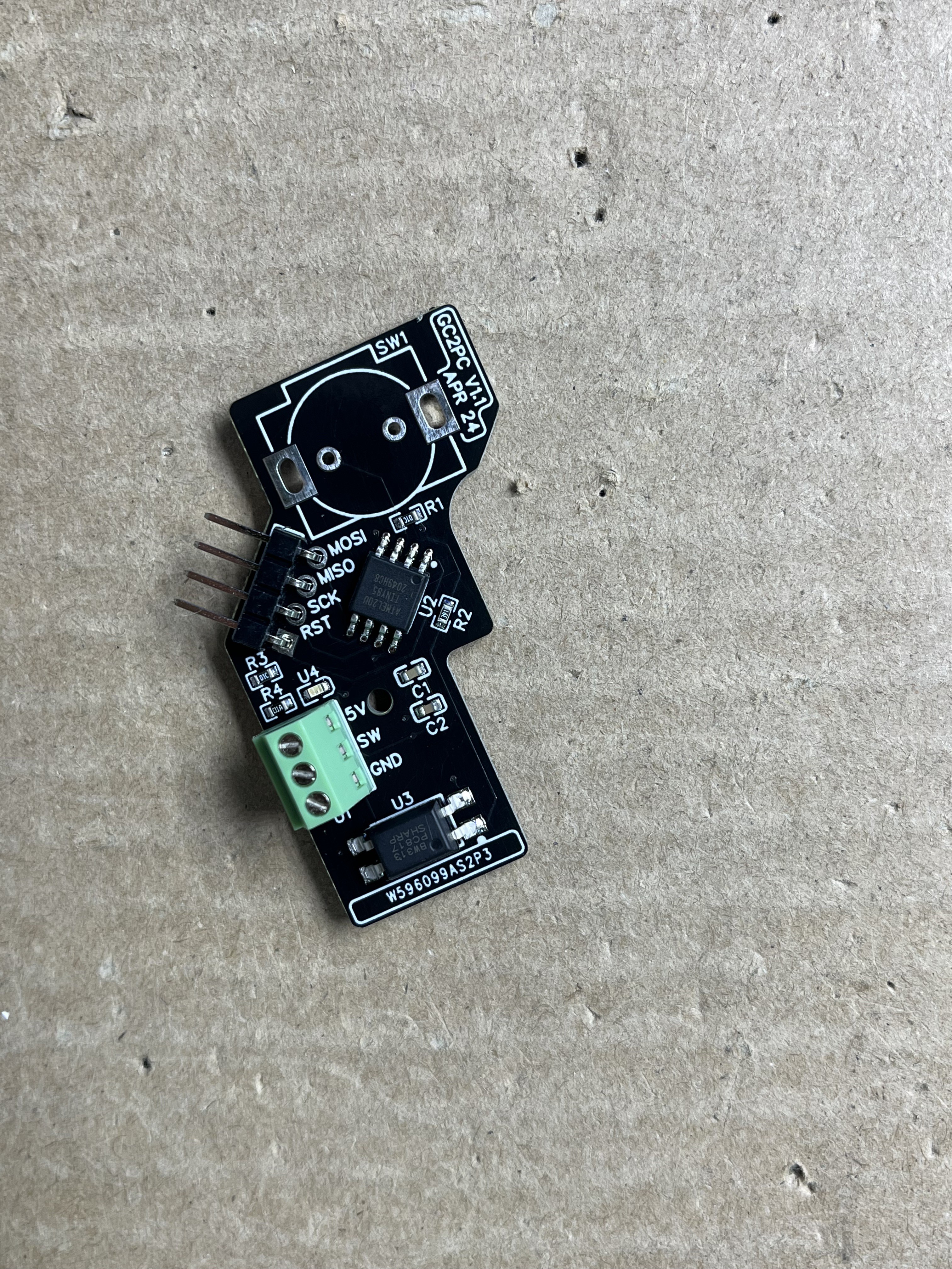
With all of this build up I'm sure you're absolutely on the edge of your seat in anticipation to see some photos of the finished boards, so here you go:


Programming the ATTiny85 with Arduino Uno over ISP
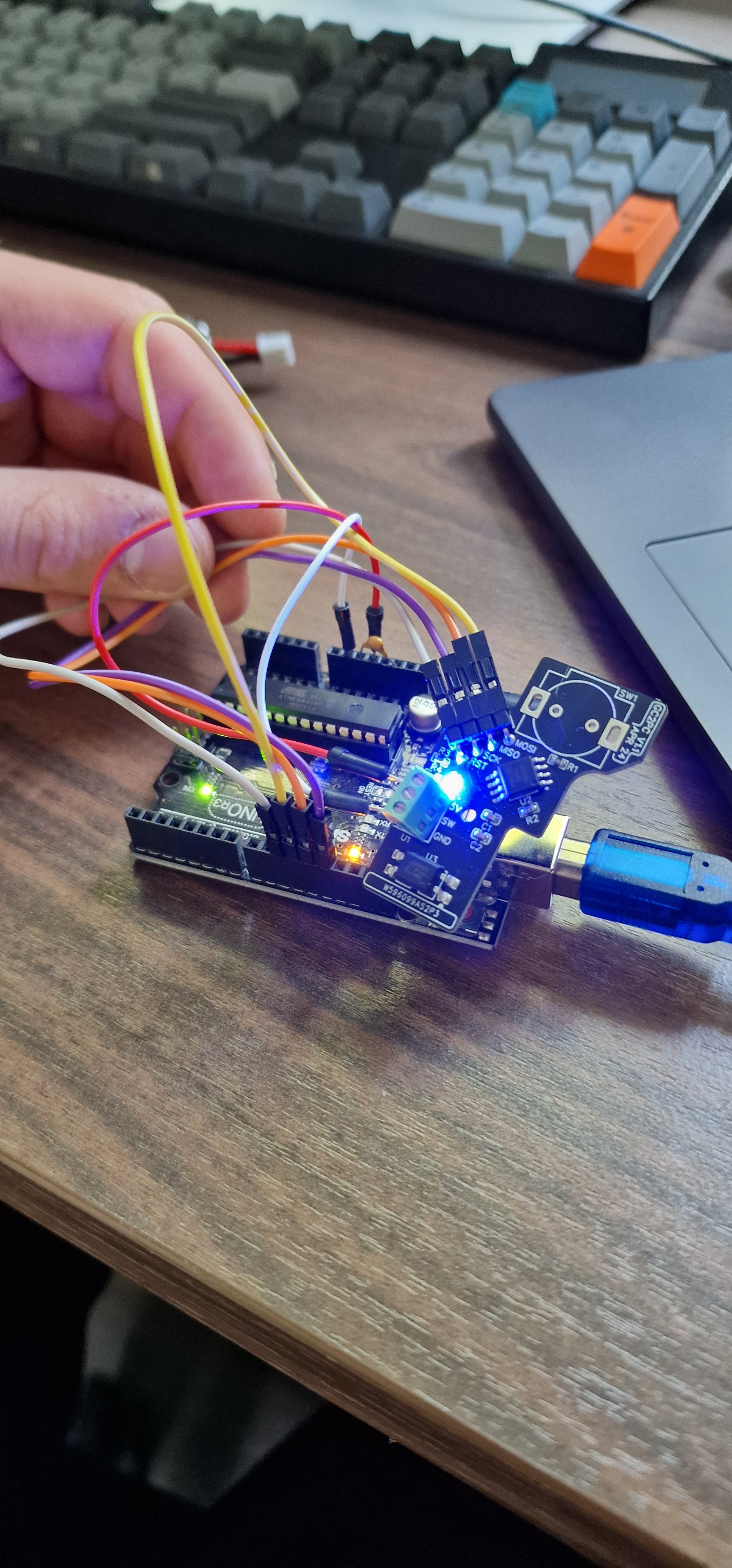
I hooked up the board to an Arduino Uno and took the following steps to program the ATTiny85:
1. Select the Arduino Uno Board.
2. Open the ArduinoISP example sketch.
3. Verify and upload to the Uno.
4. Place a 10uF capacitor between RST and GND on the Arduino to prevent it from resetting during programming.
5. Make the following connections:
| Arduino | GC2PC |
| 5V | 5V |
| GND | GND |
| 10 | RST |
| 11 | MOSI |
| 12 | MISO |
| 13 | SCK |

6. Ensure the ATTinyCore board manager library is installed within the Arduino IDE.
7. Select the ATTiny85 from the board menu.
8. The default settings should be fine but double check the clock is set to 8MHz.
10. Burn the bootloader to the ATTiny85.
11. Now the board can receive some code! Here is what I wrote to debounce the GameCube switch and allow current to pass from SW to GND for 1s.
const int switchPin = 4; // Pin connected to the switch (PB4)
const int ledPin = 3;    // Pin connected to the LED (PB3)
int lastSwitchState;     // Last stable state of the switch
unsigned long lastDebounceTime = 0;  // Last time the switch state was toggled
unsigned long debounceDelay = 50;    // Debounce delay to prevent noisy signals

void setup() {
  pinMode(switchPin, INPUT_PULLUP); // Configure the switch pin with internal pull-up
  pinMode(ledPin, OUTPUT);          // Configure the LED pin as an output
  lastSwitchState = digitalRead(switchPin); // Initialize the last known switch state
}

void loop() {
  int currentSwitchState = digitalRead(switchPin); // Read the current state of the switch

  // Check if the switch state has changed from the last read
  if (currentSwitchState != lastSwitchState && (millis() - lastDebounceTime) > debounceDelay) {
    lastDebounceTime = millis(); // Reset the debounce timer

    // Toggle the LED for 1 second if the state changes
    digitalWrite(ledPin, HIGH);   // Turn on the LED
    delay(1000);                  // Keep it on for 1 second
    digitalWrite(ledPin, LOW);    // Turn off the LED

    lastSwitchState = currentSwitchState; // Update the last switch state
  }
}
Testing
Once I had uploaded the code, I hooked up the front panel header pins on the NUC and soldered the GameCube power button to the PCB. I plugged in the power supply for the PC. Pressed the button and...
Nothing.
I made a very boneheaded mistake and assumed that the +5V DC pin on the front panel header of the NUC would be always on and could power the ATTiny85 even when the PC is off. Well, turns out that isn't the case. On top of that, I think I screwed up with the wiring of the optocoupler (I'm writing this about 2-3 weeks after doing the testing so the specific details are a tad fuzzy) because despite the embarrassingly high amount of hours I have spent watching YouTube videos and reading guides to understand how transistors gate, drain and source pins function, I still can't wrap my head around it.
So what are my options?
1. Find an alternative power source and make some minor PCB design revisions - I could tap into one of the internal USB headers on the motherboard but as you will later find out in the next log, that's no longer possible. I could maybe find another pin on the board that constantly supplies 5V DC, but I don't particularly fancy poking around and breaking anything else on the motherboard for a while so this is not my preferred choice. I don't want to bring in any external power supplies or design my own power supply, so I might go the "cop out" route and shove a small battery into the design...
2. Redesign the PCB to function as follows: Power button pressed -> NUC and ATTiny85 turns on -> ATTiny85 delivers a pulse to a transistor to momentarily close the circuit again, preventing the motherboard from registering that the button is being held in the closed position. Power button pressed again -> NUC turns off and so does the ATTiny85, however the timing would need to be precise such that the ATTiny85 delivers a pulse before it loses power otherwise the motherboard will, again, register a constant press and treat it as a hard shutdown.
3. Give in to the growing temptation to just find a momentary switch and learn to stop being such a perfectionist.
Anyway, I'm a little burnt out with the switch design right now, so I'm going to let this one rattle around in the back of my brain for a while whilst I work on other aspects of the project. If anyone has any suggestions or would like to help me with the PCB design it would be MASSIVELY appreciated.
 Jamie
Jamie
Discussions
Become a Hackaday.io Member
Create an account to leave a comment. Already have an account? Log In.