 insidepony
This ongoing project consists of a PCB powered off an Arduino.
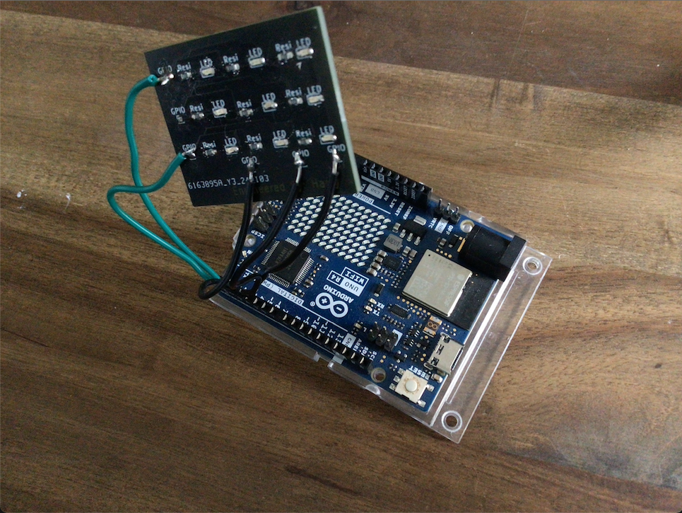
As you can see from the image there is a wire cut off and you may even think why not use a GPIO pin coming out of the board instead, the reason is because there was meant to be a GPIO pin there but we made some mis-calculation's on sizes so we couldn't get a GPIO pin to fit the wires we had so we just soldered one one making things very fragile.
My name is Harrison and I am only in year 5 so some of this may be a bit simple but still I hope you like it!
If you would like to make one please have a look at the instructions here on the project.
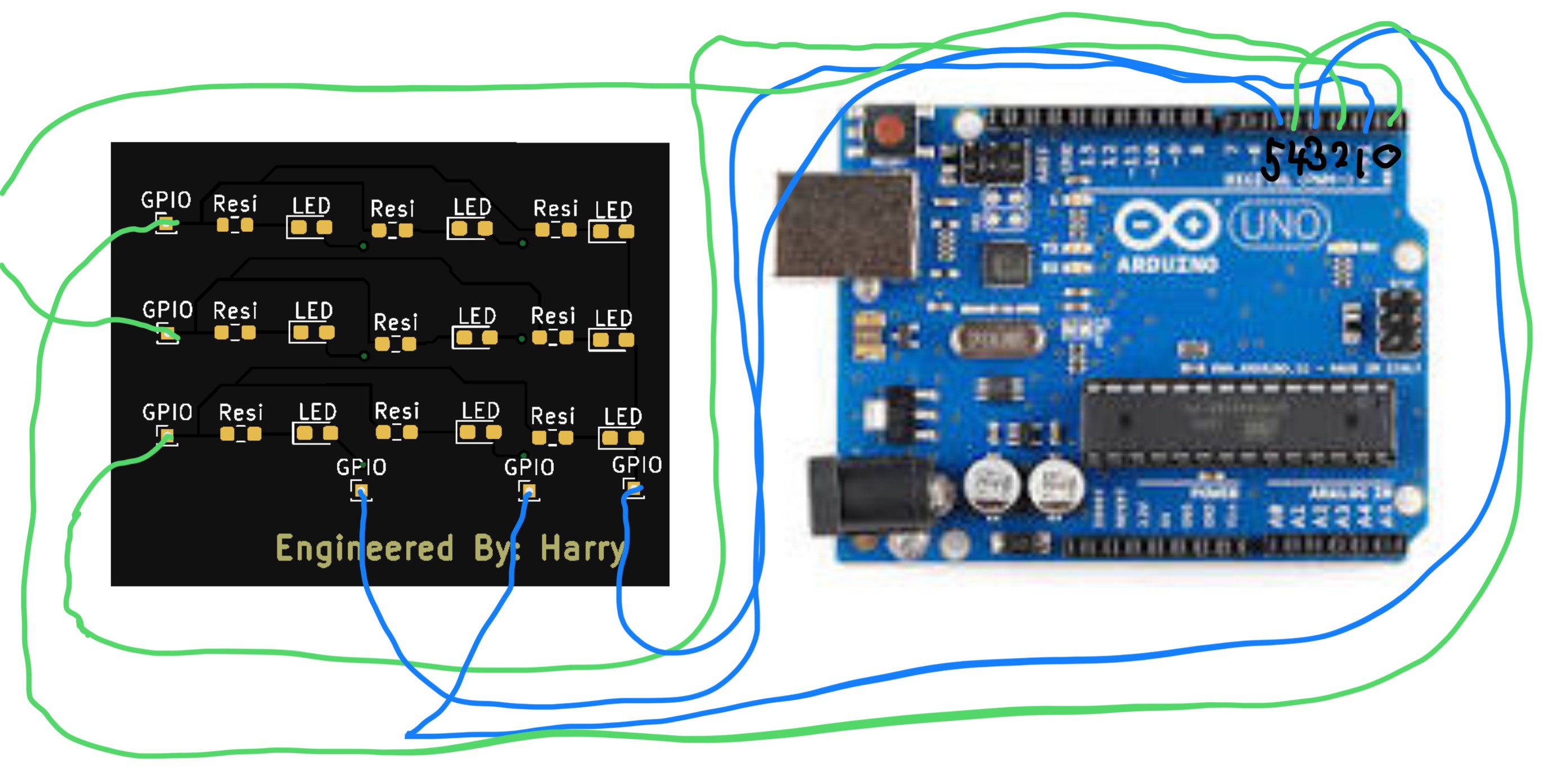
I have also added some sample code but that will mean that you need to plug your wires the same way as I do so have a look at the image bellow also listed in the gallery and instructions.
Thank you
 Non-ICE
 Alexander Ryzhkov
 Stefan-Xp
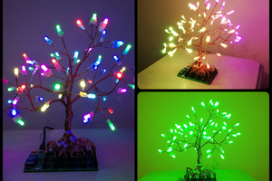
 Paczkaexpress