 Sebastian
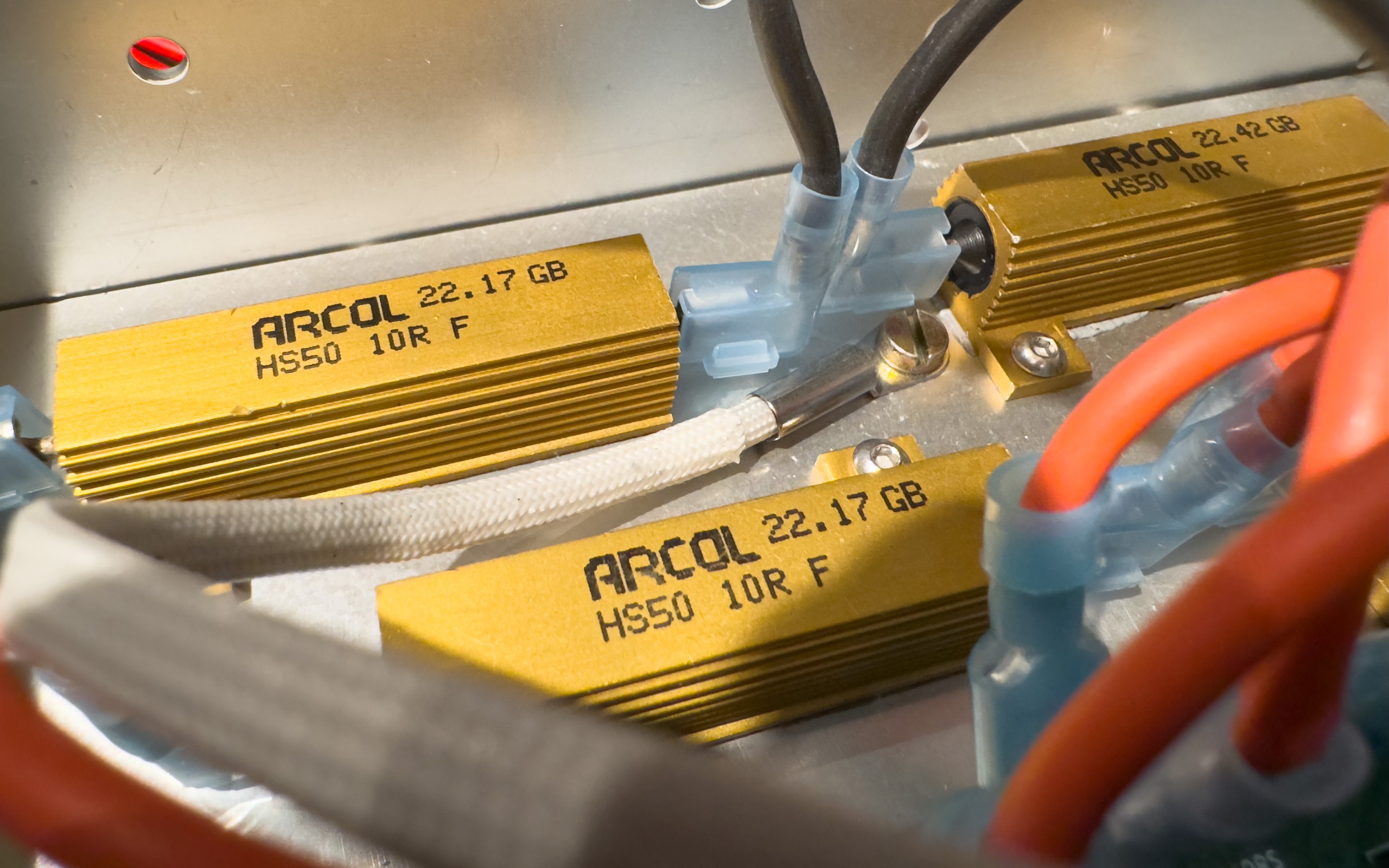
In this application the focus is on power handling capability, not so much a high resolution (high number of resistance values) or precision. This is why the topology used in the Programmable Precision Resistor is not as suitable for this application as it has been before. Also my ELMA cases are really small (and I mean really small, so thermal considerations will be challenging), so I can’t simply increase the number of power resistors and relays in the process. That’s why I’ll stick to the original plan of using 8 power resistors.
Instead the idea is to find a topology where I can select different resistance values by either connecting the resistors in series or in parallel. Let’s first have a look at a circuit for only two resistors.
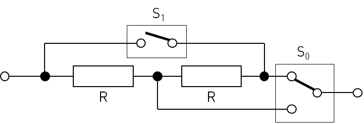
For this design I assume that both resistors are identical, both in their resistance value R as well as their power rating P. It’s very obvious how this circuit works, but here are the current paths for the different switch states anyway:

Since the math behind this is really simple, here are the results without any further explanation.
| S0a | S0b | R0 | P0 | I0 | U0 |
| 0 | 0 | 2R | 2P | √(P/R) | 2R√(P/R) |
| 0 | 1 | R | P | √(P/R) | R√(P/R) |
| 1 | 0 | 0 | unlim. | unlim. | 0 |
| 1 | 1 | R/2 | 2P | 2√(P/R) | R√(P/R) |
And now we have our basic building block that we’ll use in the next post of this series.
Discussions
Become a Hackaday.io Member
Create an account to leave a comment. Already have an account? Log In.