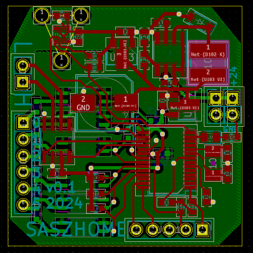
Board was design in KiCad. Schematic and board below:
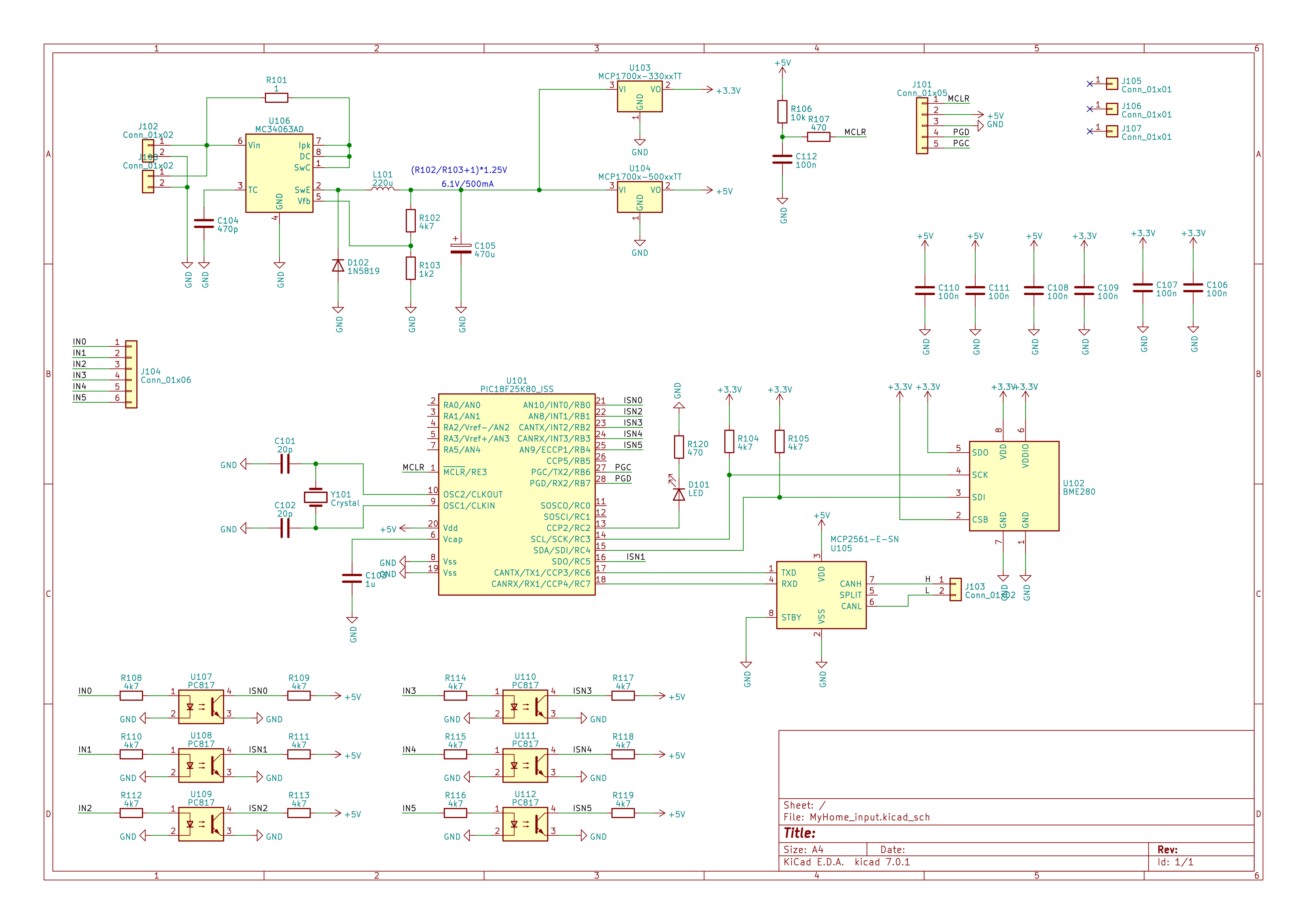
Design is quite ordinary without any fancy solutions.
Optocuplers on the inputs are on the same ground as rest of the circuit, but it is much easier, cheaper and smaller solution then resistor divider and protection circuit.
A little problematic was connection between BME280(3,3V) and PIC(5V), but fortunately microchip have bulid-in SMBus hardware support which allows to work without any additional hardware.
Talking about BME280: small gap in ground was made for thermal isolation (we will see how it works in future). Second future are three holes near BME. I made them for future, because I plan to play with pressure measurement and it allows to connect some small manifold.
Discussions
Become a Hackaday.io Member
Create an account to leave a comment. Already have an account? Log In.