Close
0%
0%

Bootstrap 3D Printer

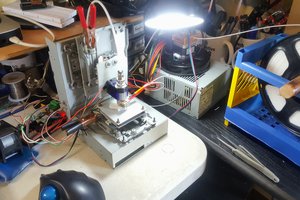
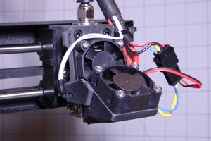
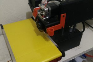
Bootstrap: A large volume 3d printer that can be built at home without requiring any custom 3d printed or machined parts.

Public Chat
Similar projects worth following
It has always bothered me a bit that most guides to create a 3d printer from scratch require sourcing custom 3d printed or machined parts. It feels like that thing about needing scissors to unpack your new scissors. Also, I didn't want to build a kit because I have a lot of (high quality) parts that I want to reuse. Unfortunately I was a bit optimistic dismantling my working printer when building a new printer, "slippy". This printer never worked and left me in a state of limbo, so I decided to start over with a new design.

The printer doesn't have to be pretty, but it does have to print high quality parts in order to upgrade it.

WIPKAT BOOTSTRAP

Core Concepts

I want to build a printer without making use of a kit, custom 3d printed or machined parts.  This rule is mostly about the structural part of the printer, not the printhead / nozzle / extruder etc. It should be made from generic parts so that we have some room to improvise and customize.

Dual Motor Setup

One of the main features of the printer is that it uses a second motor where you'd normally use a pulley. This is because:

  • I have a lot of motors laying around
  • A motor isn't that much more expensive than a pulley + bearing + mount + axel
  • It is harder to align a pulley, especially when only using generic parts, than mirroring the motor.
  • You divide the load between the 2 motors, they can run cooler or be combined for more torque.
  • Counter rotating the motors before a print is a neat way to tension your belts.

Scale

I think many large scale printers nowadays are generally scaled up versions of small printers. They often use the same (miniature) rails, gantry designs and kinematics. However, sizing up changes the relative weights of the components. Where a motor used to be too heavy to be on a moving part of the printer, and complicated kinematics like CoreXY came to the rescue, on larger printers a small NEMA17 might not add that much weight relative to the gantry weight. This allows us to simplify the design of the printer, by having the X motors ride along with the X axis.

I'm also investigating whether MGN rails are really worth it on this scale, because they are very expensive when you need longer rails. The HGR15 rails seem more suited to the scale of the printer I have in mind, but obviously this is a gamble as there are not that many examples out there in the community using these rails, nor are there any parts available that interface with the larger carriages.

To offset for the increased weight I am using a lot of motors in  dual / quad motor setups (4x Z, 4x Y, 2x X, 1x E) combined with TMC5160 motor controllers, which should give me enough power to connect pairs of motors to a single controller in parallel (because the main board doesn't have 11 slots for motors, only 8). To combat stresses on the frame and vibrations I'm going with 3030 frames, which also limits my options when shopping for parts that fit nicely to the rail (everything is 2020)

The Goal

The initial goal for this printer is to be good enough to print its own upgrades, while providing enough quality for my day to day (hobby) 3d printing needs. Then keep making it better and better, I have a lot of ideas, like multiple extruders, a heated chamber, and other toolheads like lasers or maybe even paintbrushes? We'll see!

  • 1 × BigTreeTech Manta M8P v2 The main controller board
  • 1 × Raspberry Pi CM4 Wireless, 8 GB RAM, 16 GB eMMC + Antenna Kit + Heatsink
  • 1 × Mean Well 24v PSU RSP-320-24
  • 1 × Jonsbo Case D31 Mesh Screen Black
  • 3 × CPU Fan Corsair LL120 RGB, modded to run ARGB

View all 26 components

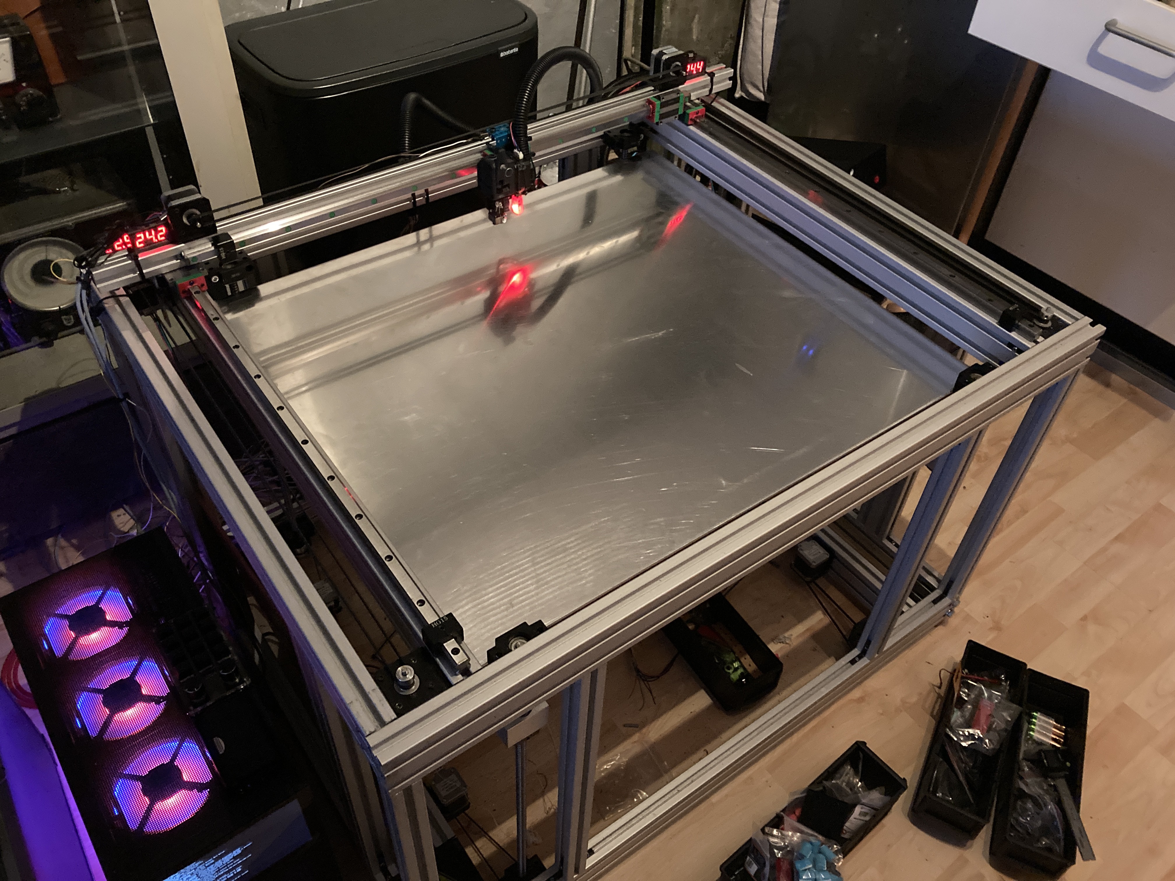
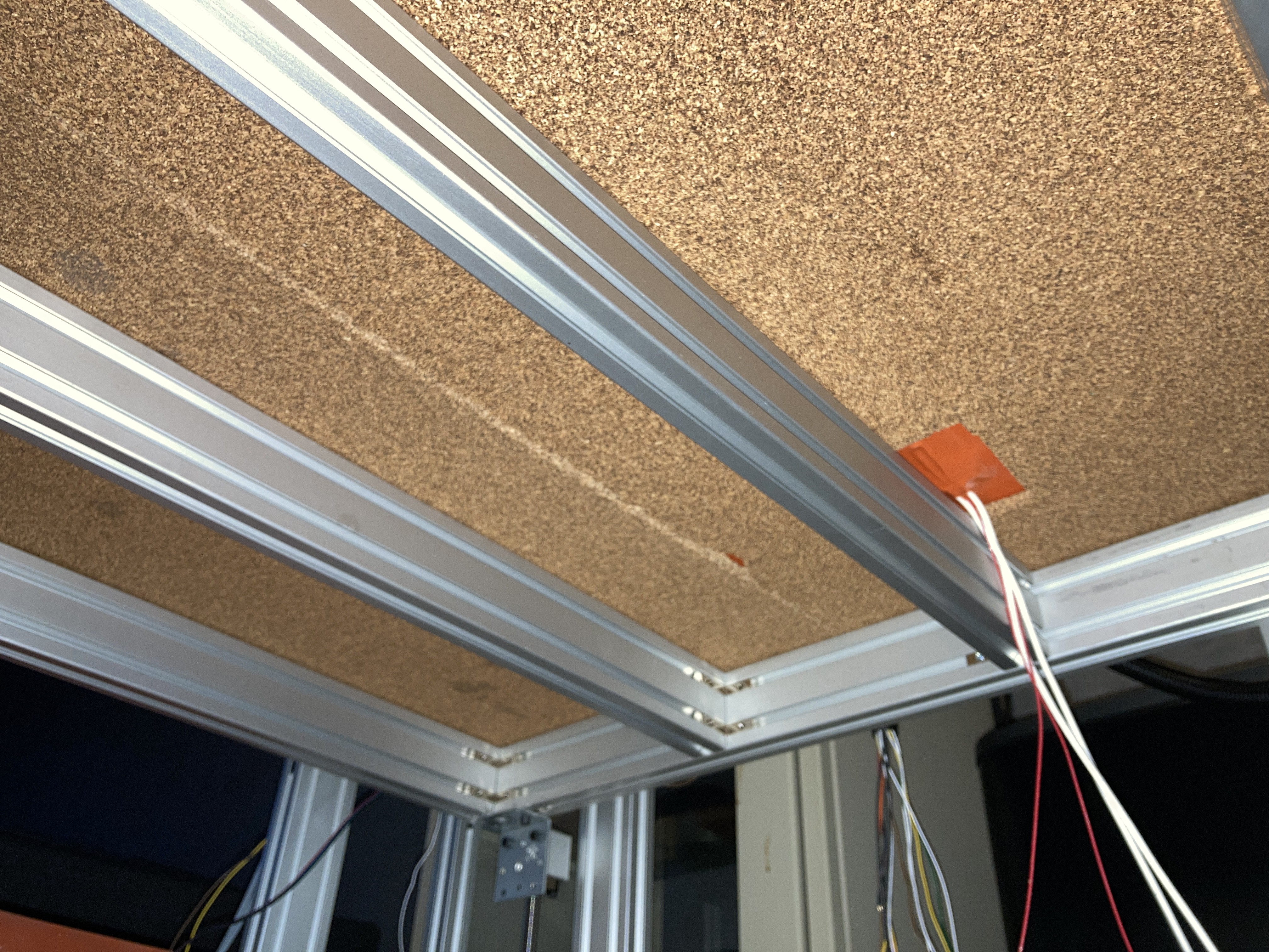
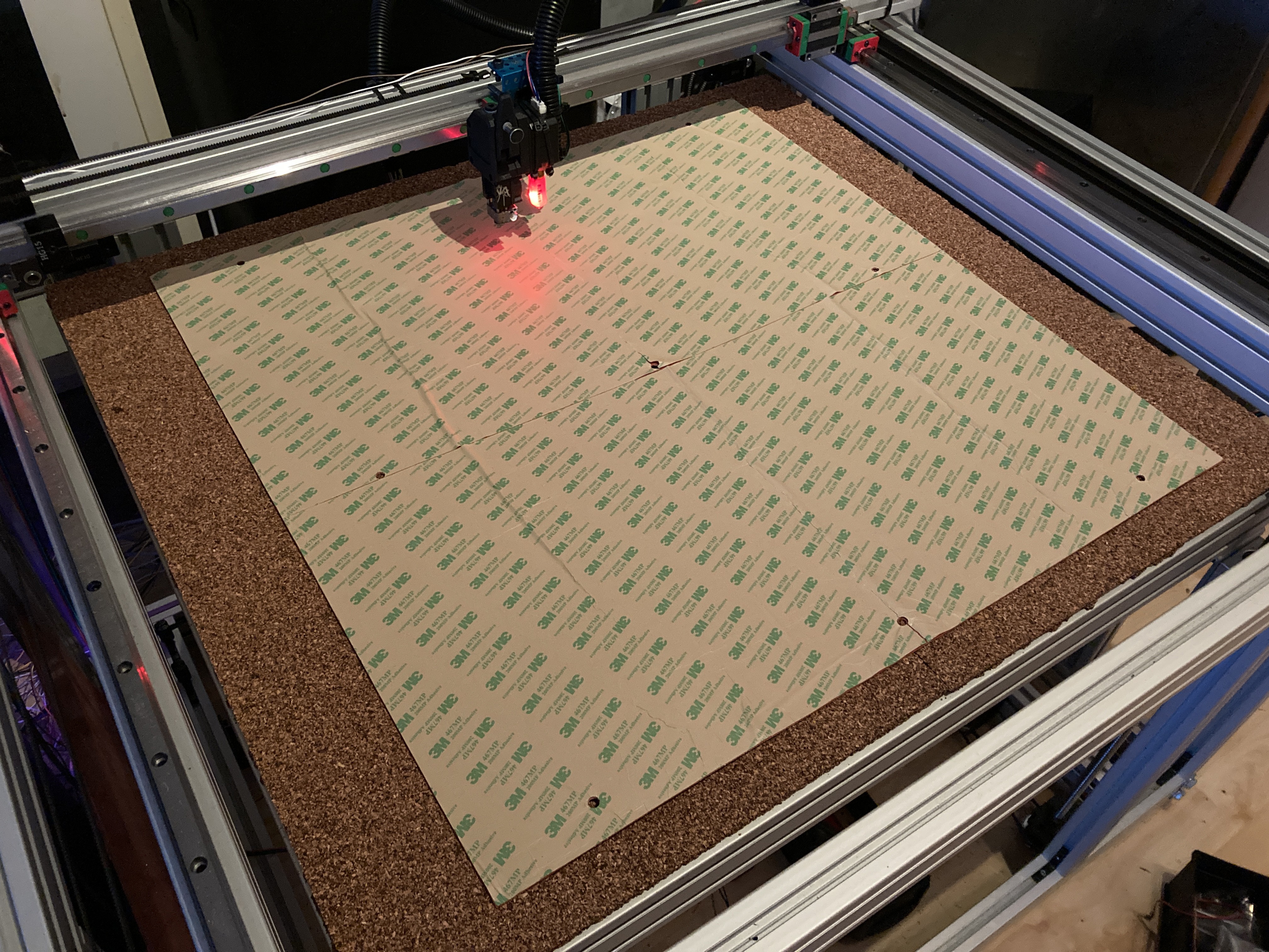
  • Print bed installed

    E/S Pronk05/30/2024 at 19:55 0 comments

    Finally received the silicone heat bed for the print bed. I first made a layer with cork, then added the heater and the aluminium plate. I think i’m still going to add a build-tak removable plate…

  • Automatic Belt Tensioning

    E/S Pronk05/09/2024 at 03:47 1 comment

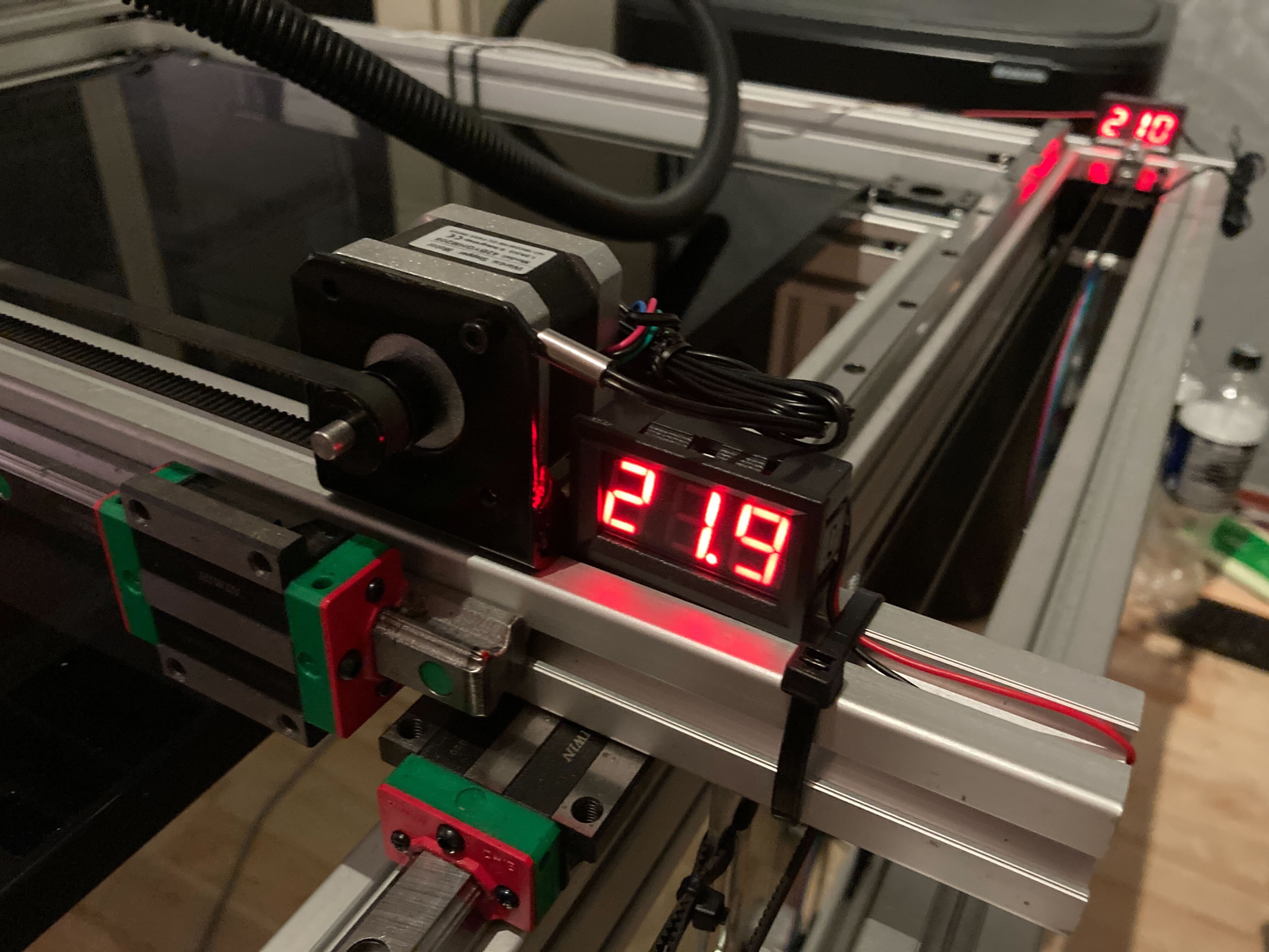
    I'm currently waiting while components are coming in slowly, in order to finish the bed. In the meantime I found these digital thermometers so I can keep track of my motor temperatures, which is probably a bit frivolous, but does look cool :)

    Automatic Belt Tensioning

    Now, having 2 motors for an axis, one on each side, allows for a cool trick. We can counter-rotate the motors and add tension to the belt, and as long as we power the motors with enough torque they should be able to hold the tension between them. 

    One minor issue is that for this to work they both need their own motor controller, and currently I only have a single controller attached to both X motors (in parallel), while the Y controllers are split between left and right, not sharing a belt. So I ordered a can-bus extension board for the extruder which comes with a dedicated TMC 2209, freeing up one motor controller on the main board and allowing me to clean up some wiring along the way.

    Initially I will just add some manual offset to just one of the steppers during the homing procedure while the other holds its position, but what I really like to try, later, is to use TMC's StallGuard to get an even tension regardless of the initial state (tension) of the belt.


  • Initial speed test 700mm

    E/S Pronk05/03/2024 at 17:18 0 comments

    I finished the wiring of the print head and set up the homing procedure. This is the first speed test, the print head travels 700mm each move. This is not the maximum speed of the printer, this is the maximum speed I felt comfortable with trying, at this time. Acceleration is set to 2000mm/s^2 which can probably be increased, I didn't feel like calculating the actual speed the print head is traveling at at its top speed, but it is below the set max speed of 1000mm/s.

    For the time being, I'm happy with the results :)

  • PCIe mini XLR brackets

    E/S Pronk05/03/2024 at 00:47 0 comments

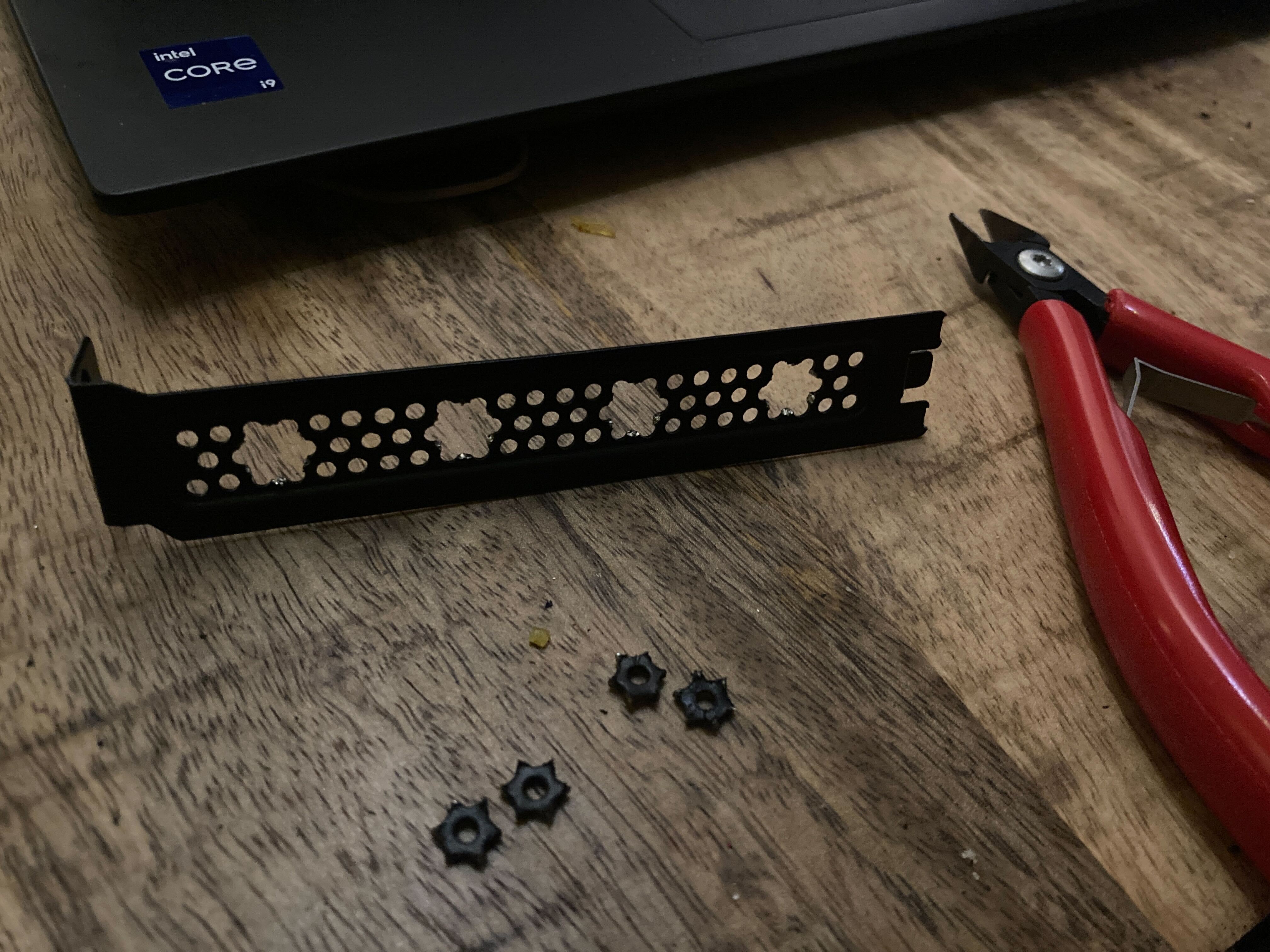
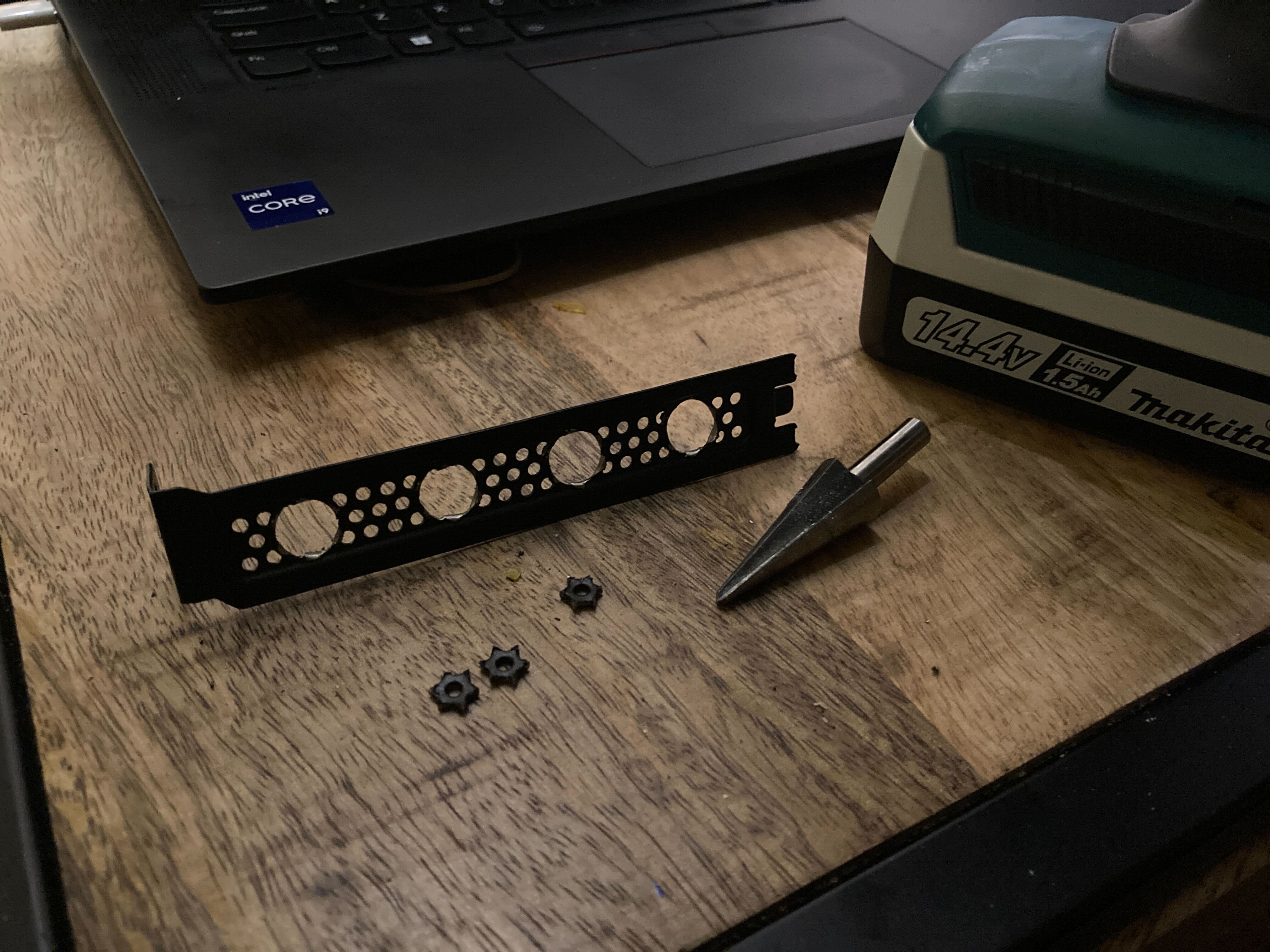
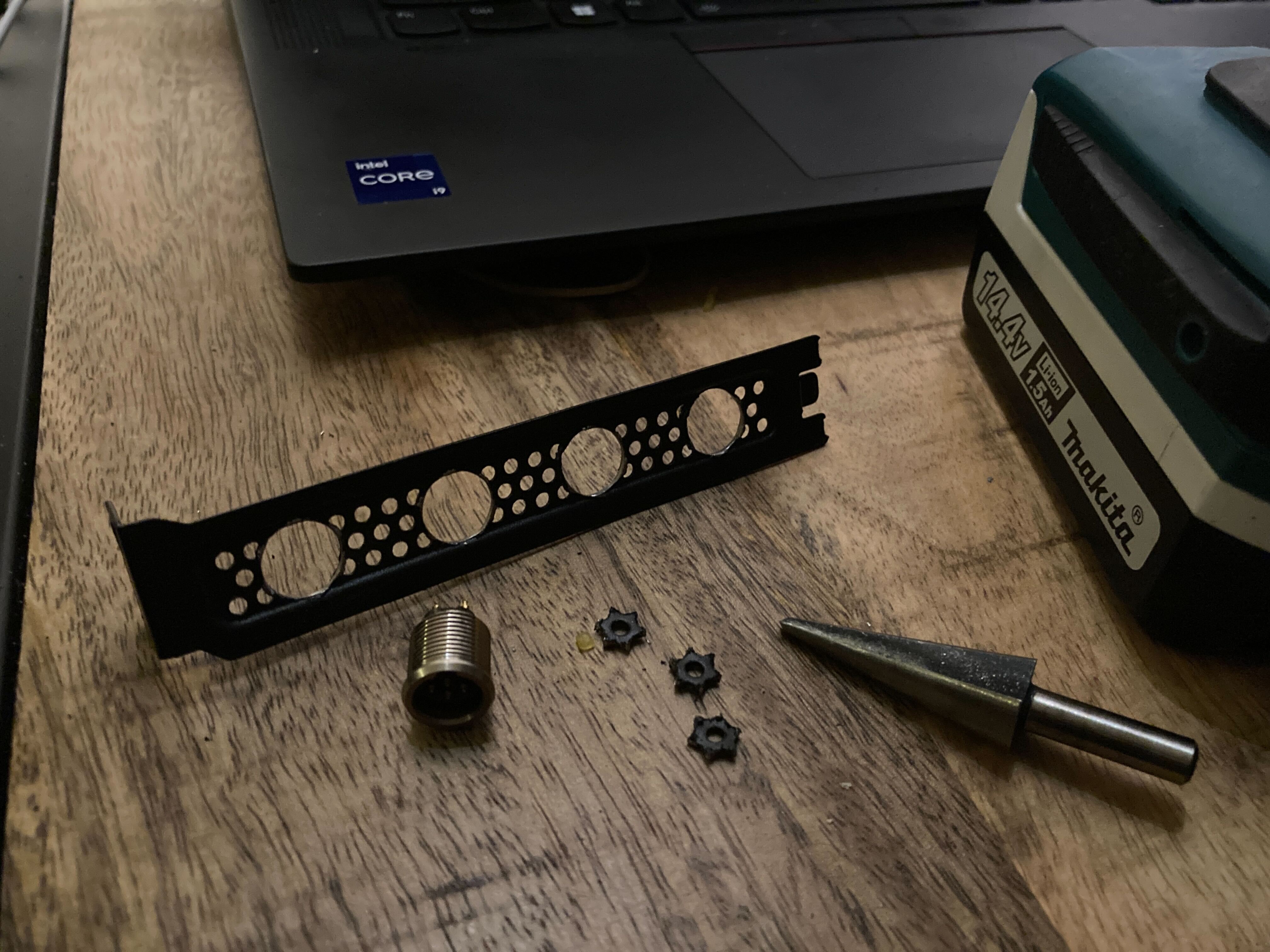
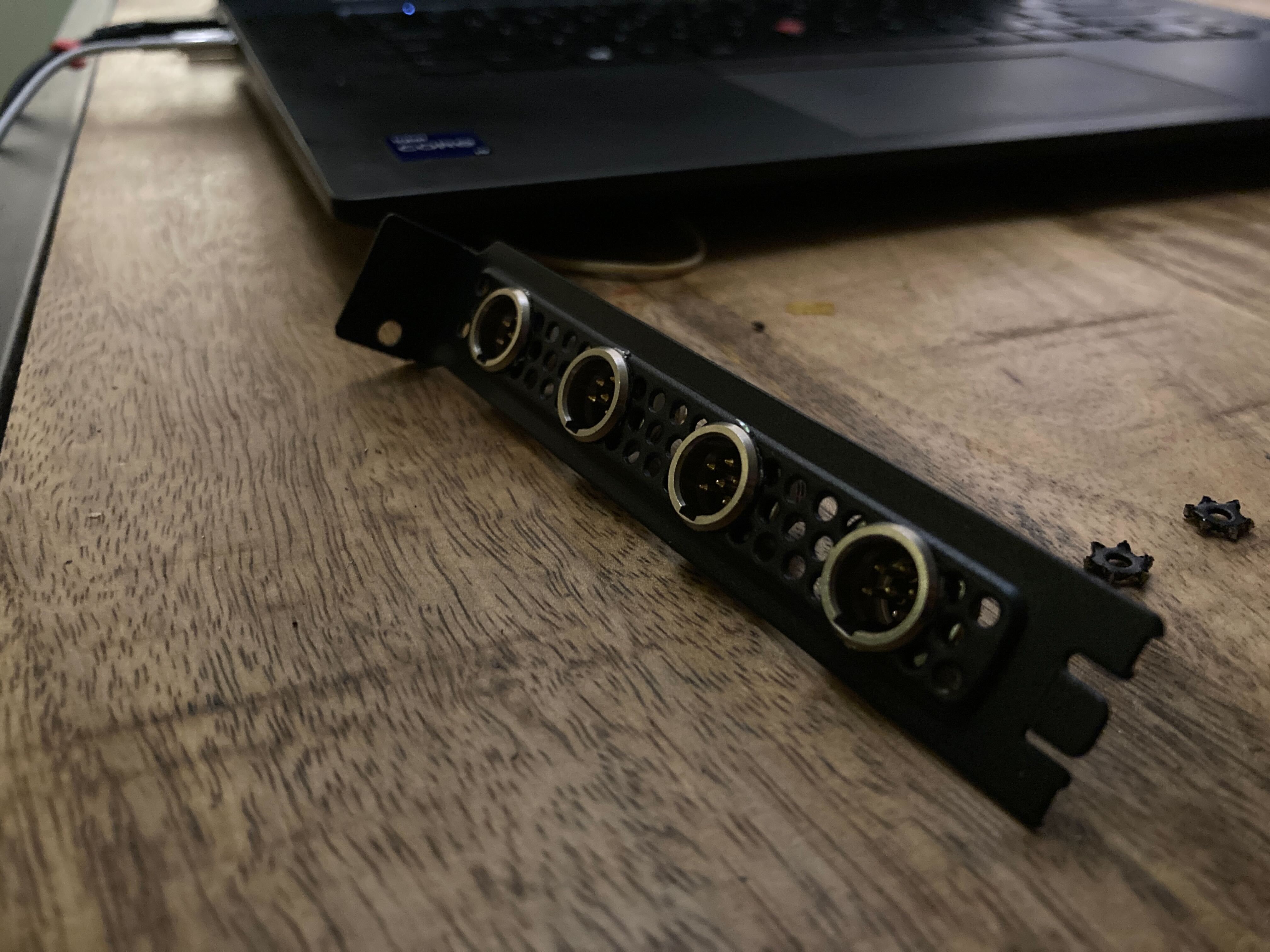
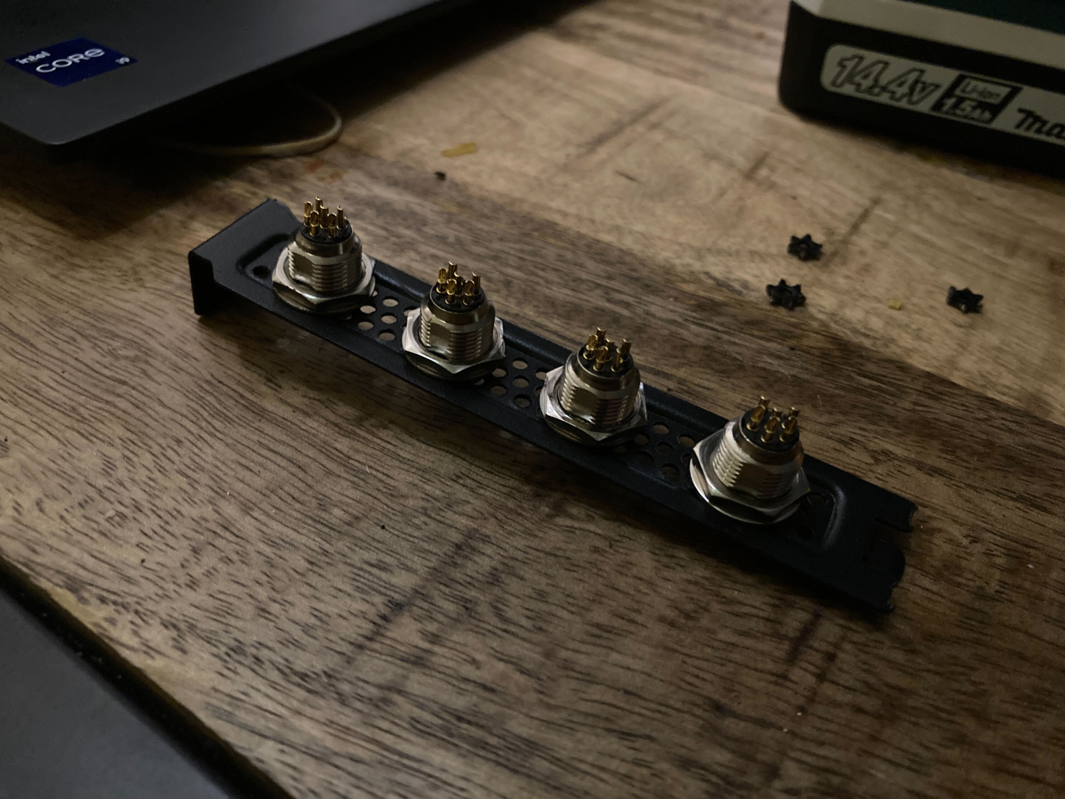
    I'm trying to connect my motors to the board in a nice way. I thought it might be nice to use mini-XLR connectors and drill holes in a blank PCIe bracket. 

    I do not recommend doing this with a hand drill

    However, this is my personal log of how I did it with pliers and a handdrill...

    Step 1: Cut out parts of the grill where the connectors are going to be placed

    Then, with an "erbauer cone drill bit" make the flower shapes into hole shapes but do so with the drill put IN REVERSE.

    They will still be too small to fit the connector, but now you can carefully try drilling with the drill in the forward direction. Make small increments until the connector can be pushed through

    Then all that's left is finish up, and in a later post we'll be wiring the motor controller outputs to these ports.


  • It's gonna be tight...

    E/S Pronk05/02/2024 at 01:21 0 comments

    1 mm tight to be exact... That's the margin I have to work with before things start running into each other. 

    I was a bit quick on the draw and ordered the aluminium plate for the print bed yesterday. Measured it and all seemed well. Then I tested the homing function with a temporary bed (just a glass closet door from ikea with roughly the same size as the bed) and the bed hit the bearing blocks of the ball screws all the way at the top. Did not take those into account, did not fully realize the bed would be raised past these blocks.

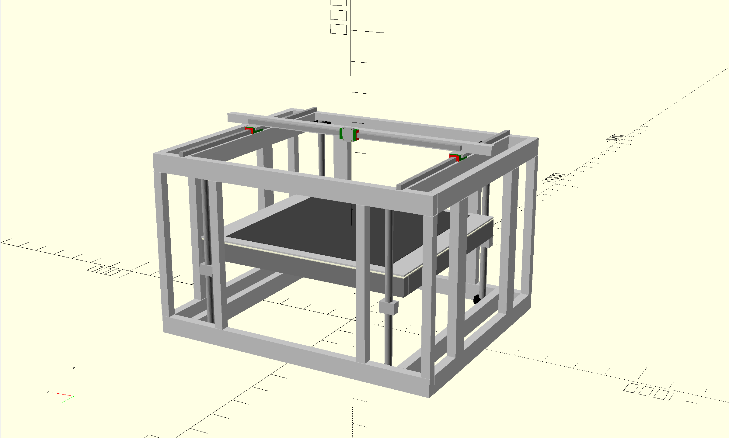
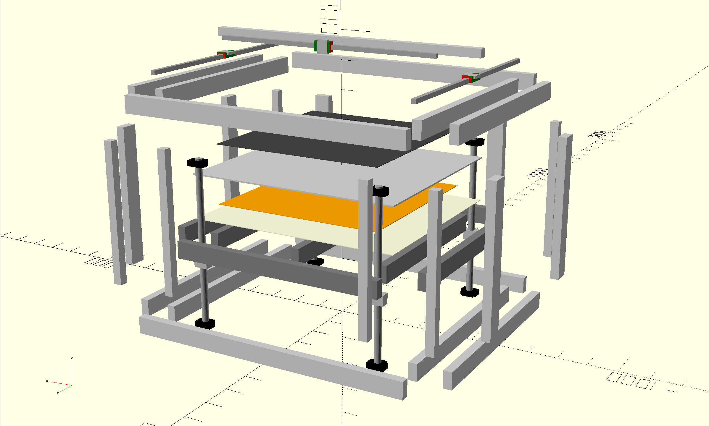
    Now, the bed itself wasn't properly tightened and it seemed everything might just fit, but just to be sure (and because it was overdue) I drew the construction in openscad and realized the distance between the bed and the bearing blocks is going to be 1mm on either side. Not the kind of margins I'm happy with when basically "winging it".

    But I just dropped 100 on the aluminium plate and another 100 on the extrusion profiles to support it, so I'm going to keep my fingers crossed and hope for the best.... otherwise I guess I'm buying a load of sanding paper and spend a few hours getting a few extra millimeters of margin somewhere....

  • Bye Bye Fingernail

    E/S Pronk04/30/2024 at 22:58 0 comments

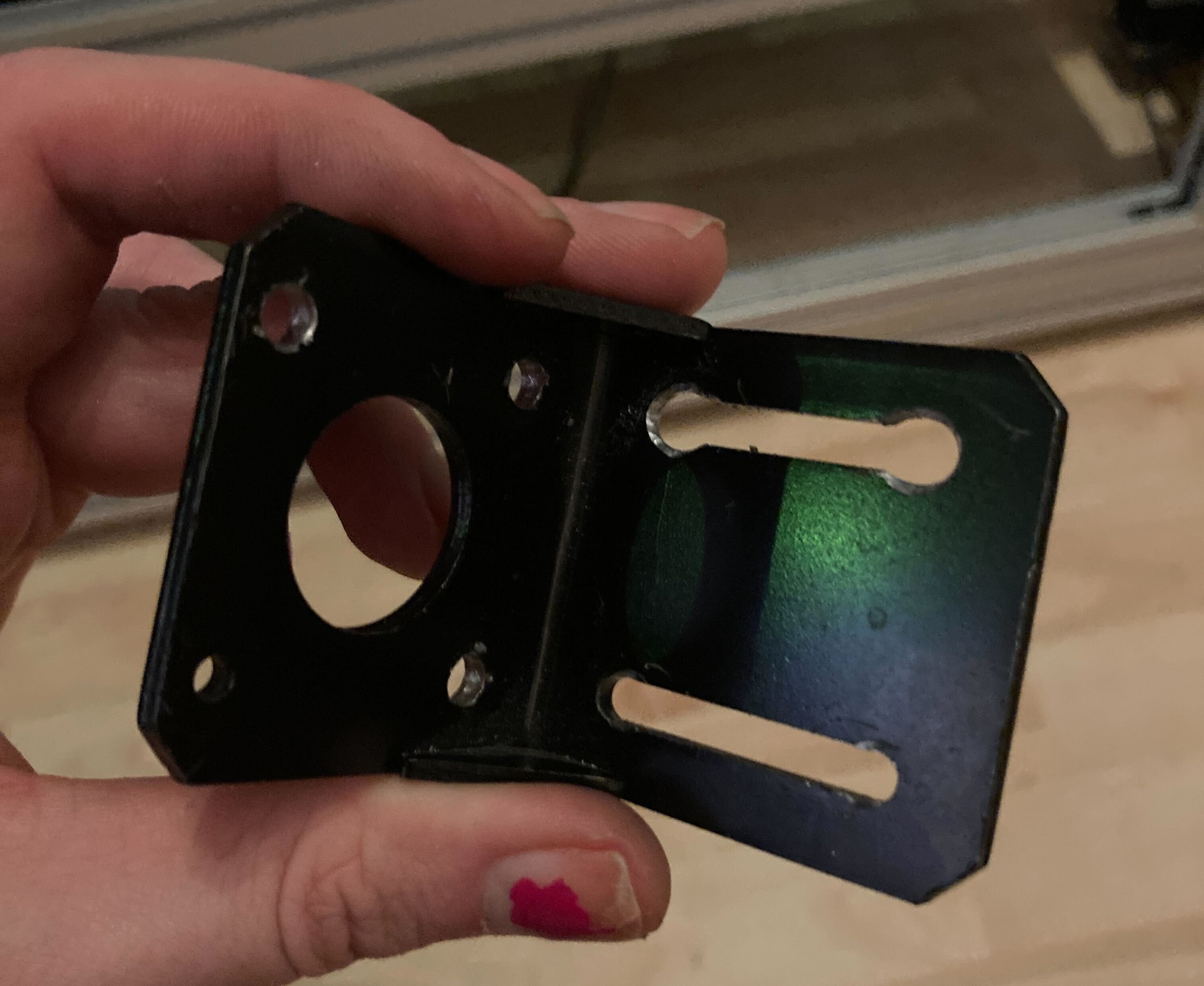
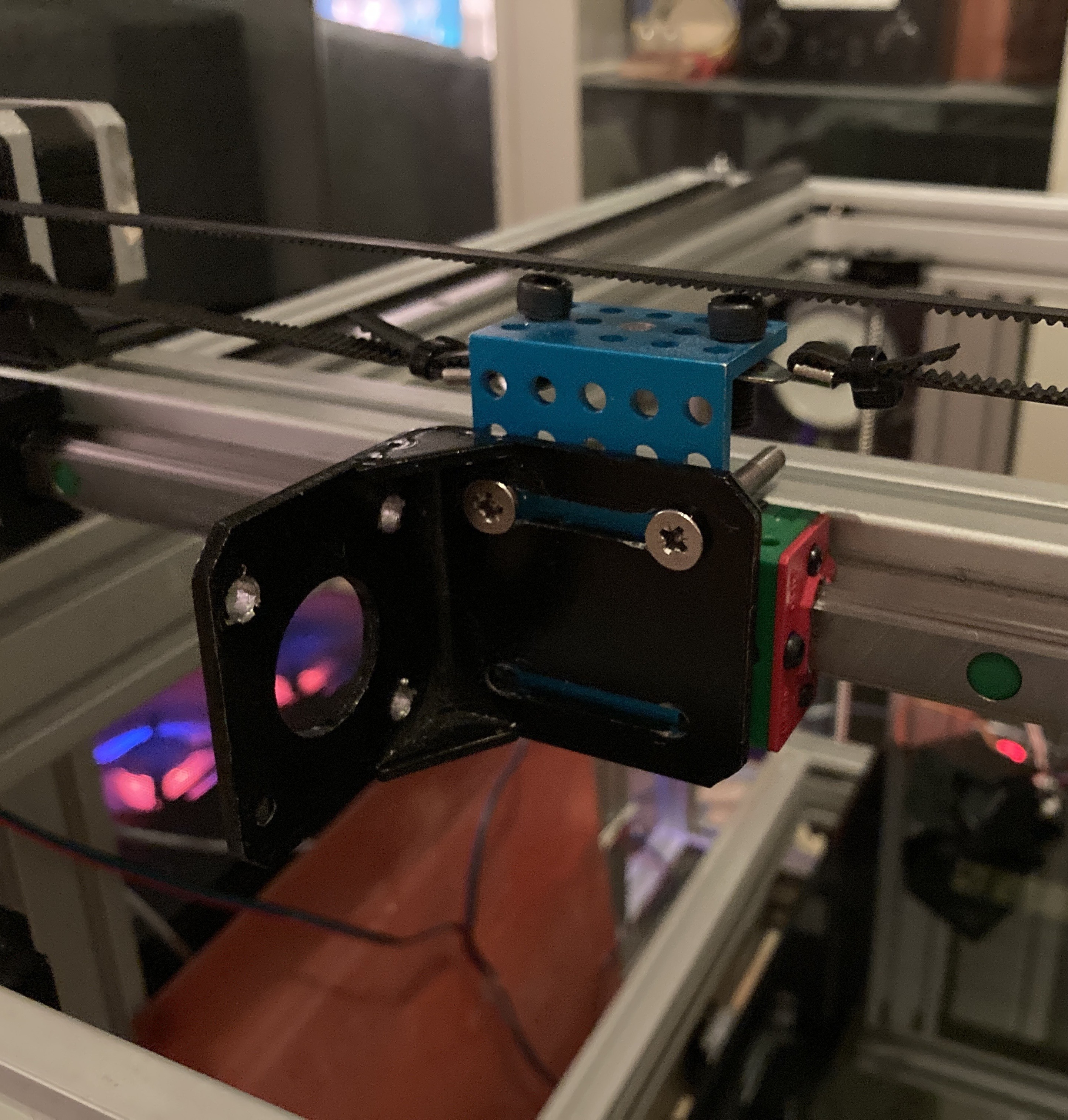
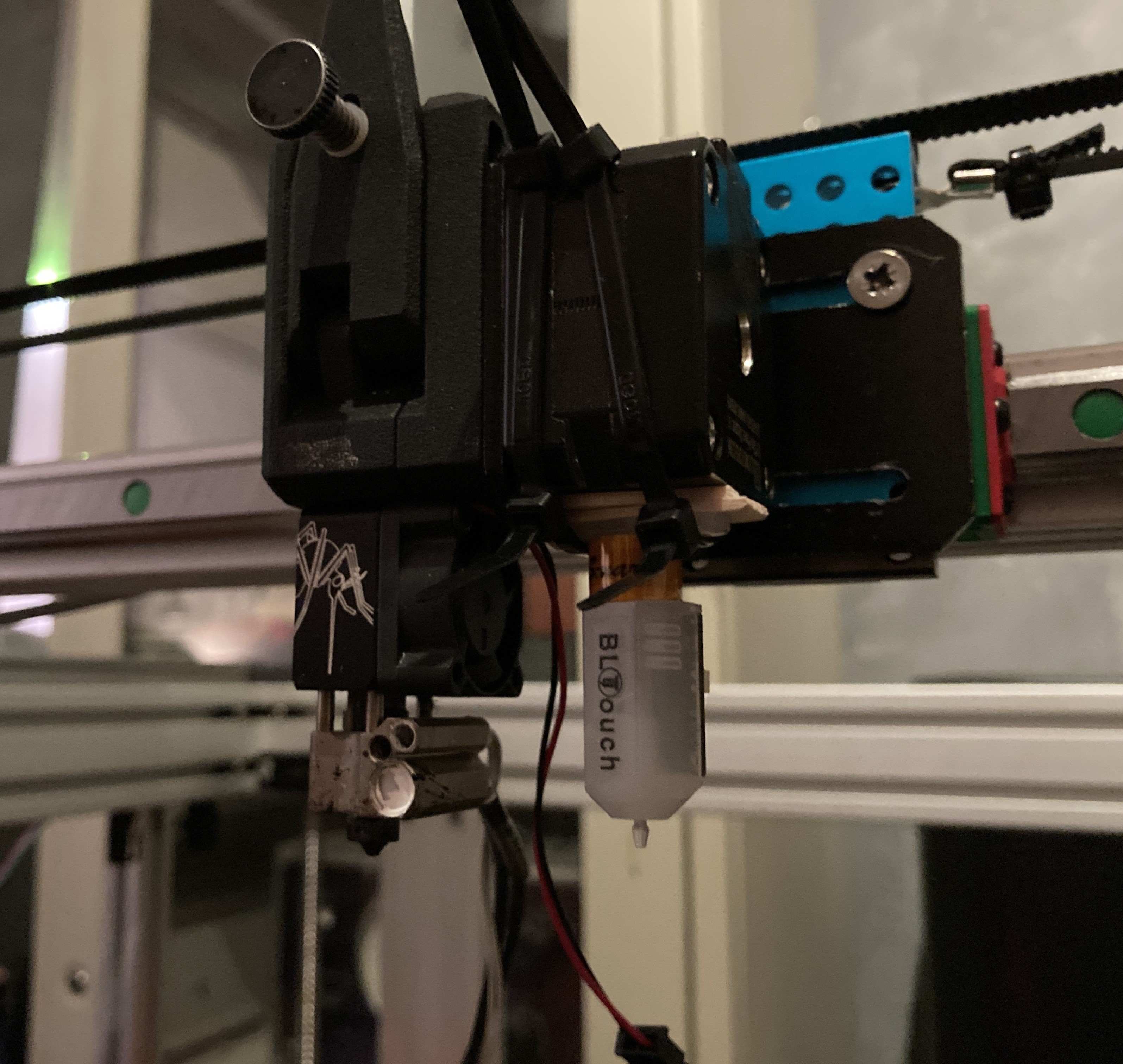
    It took me a good 40 minutes and a part of my fingernail, but I managed to abuse a standard NEMA17 mount to fit M5 bolts at the spacing required for the carriage, using a handdrill, pliers and a screwdriver.

     Installed it

    And the first extruder is in place... Now I still need to figure out where to install the BLTouch. Probably going to mount an L bracket between the motor and the extruder. <-- scrap that...

    4 tie wraps + 2 pieces of a wooden fork as a spacer. That BLTouch is going nowhere...

  • Sensorless Homing

    E/S Pronk04/30/2024 at 19:28 0 comments

    Adding end-stops is easy, but only when you can make or buy something custom to fit a rail. Since I'm using 3030 extrusions, finding such parts is a pain (everything is 2020). So I am trying out "sensorless homing" which uses the StallGuard technology in the TMC5160 drivers to detect when a motor stalls due to the carriage hitting an end-block.

    Just following the Klipper documentation on this goes a long way in getting it set up, the only thing I noticed that they forget to mention is that you have to make sure your belts are properly tensioned.

  • The Frame

    E/S Pronk04/29/2024 at 21:47 0 comments

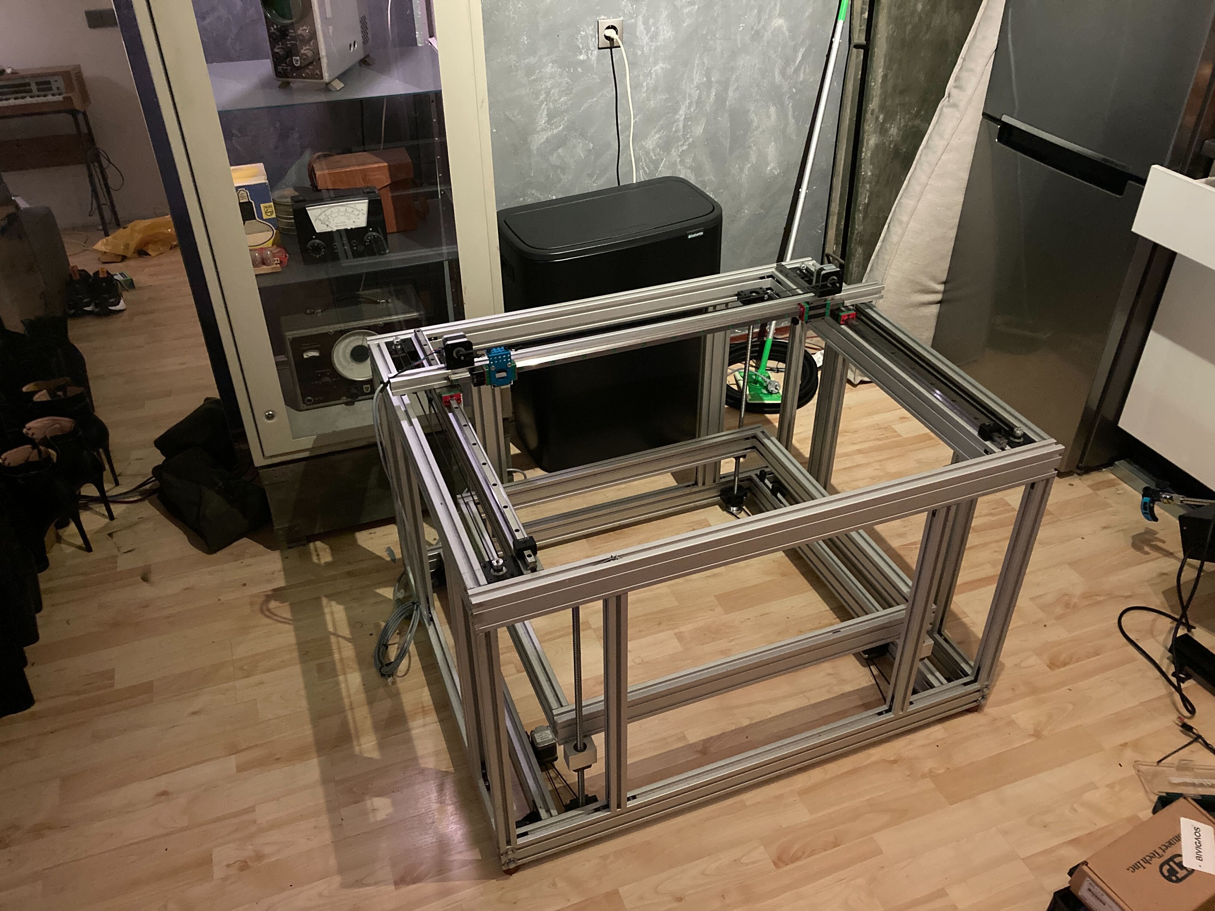
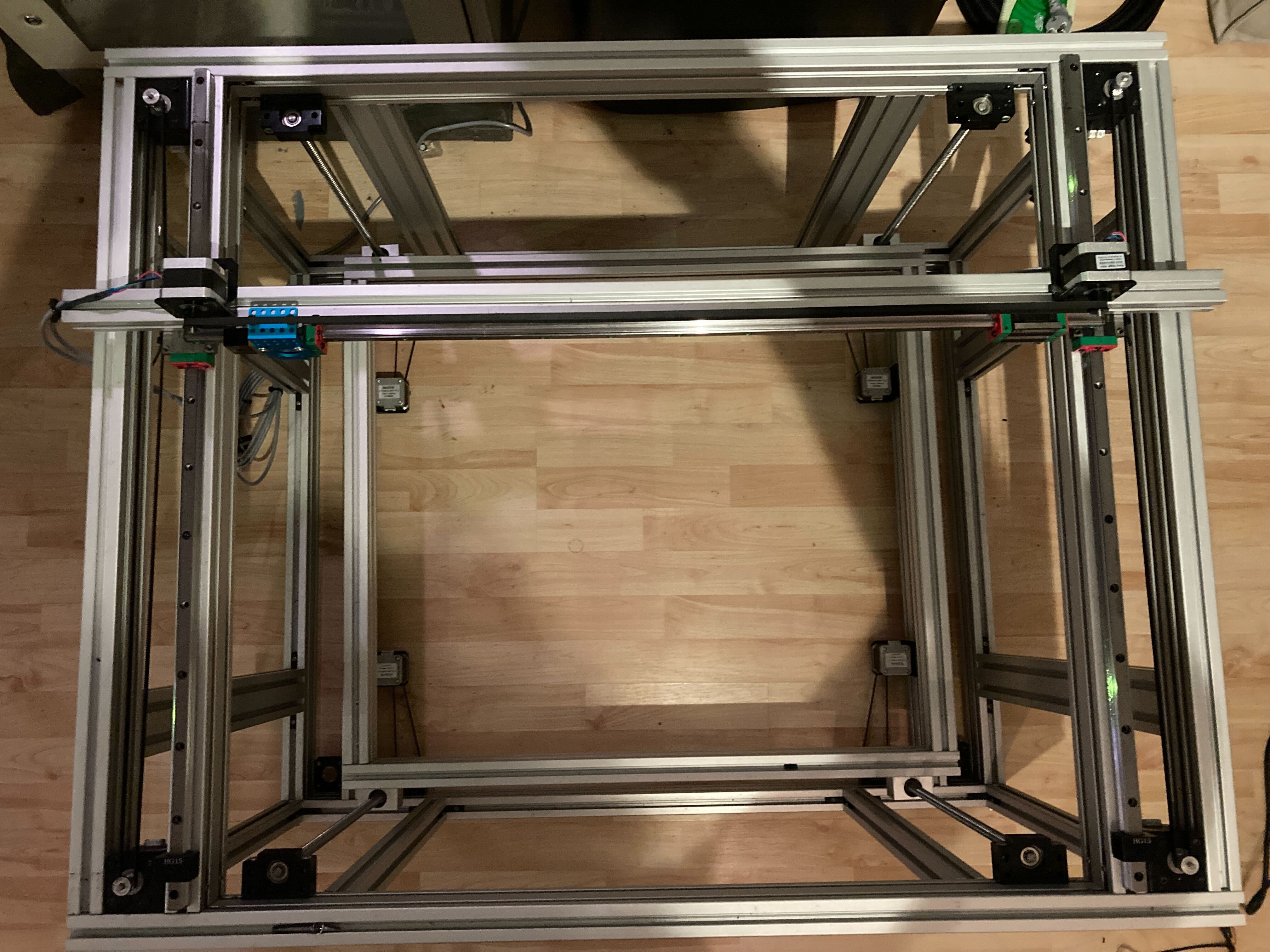
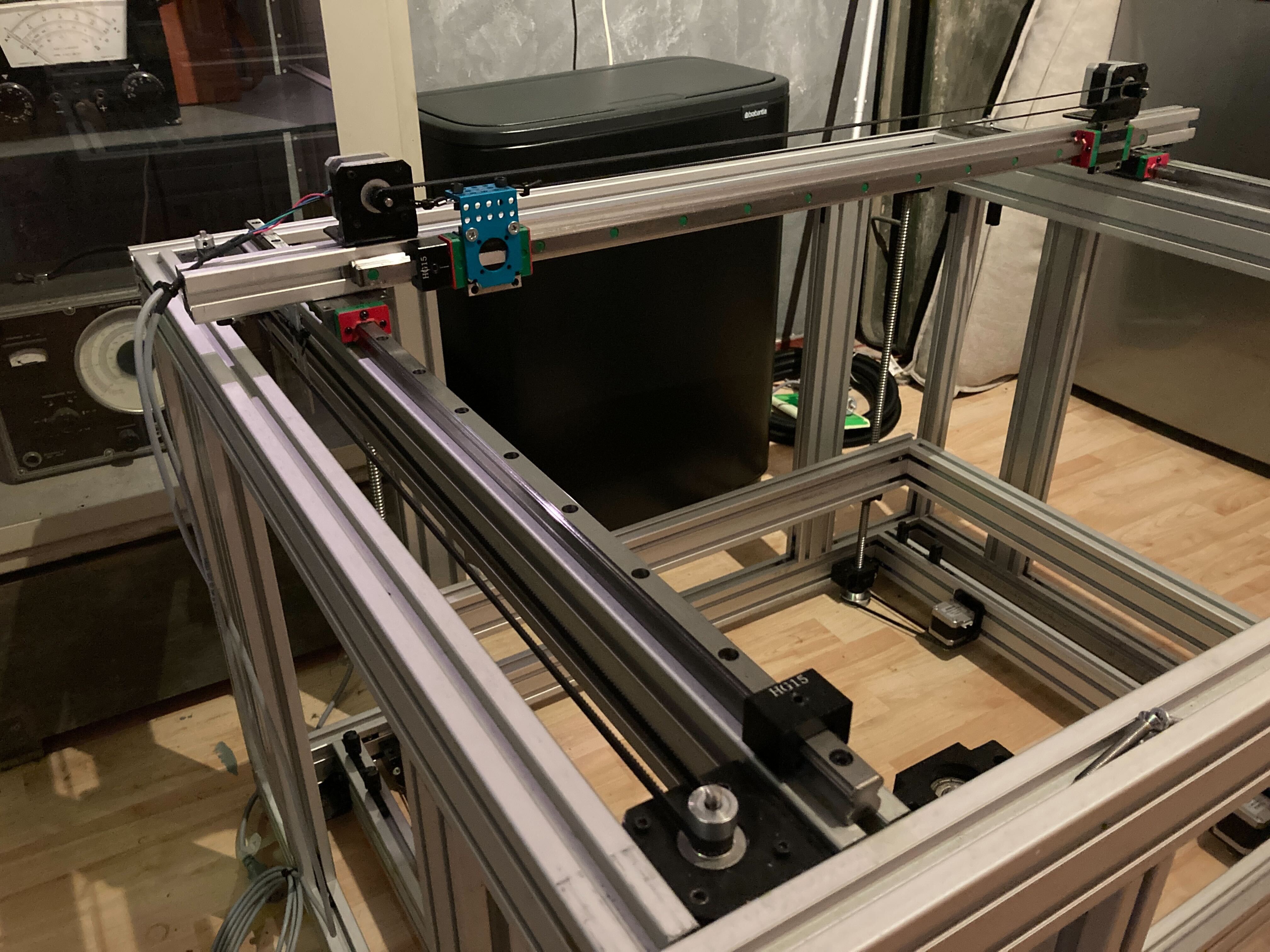
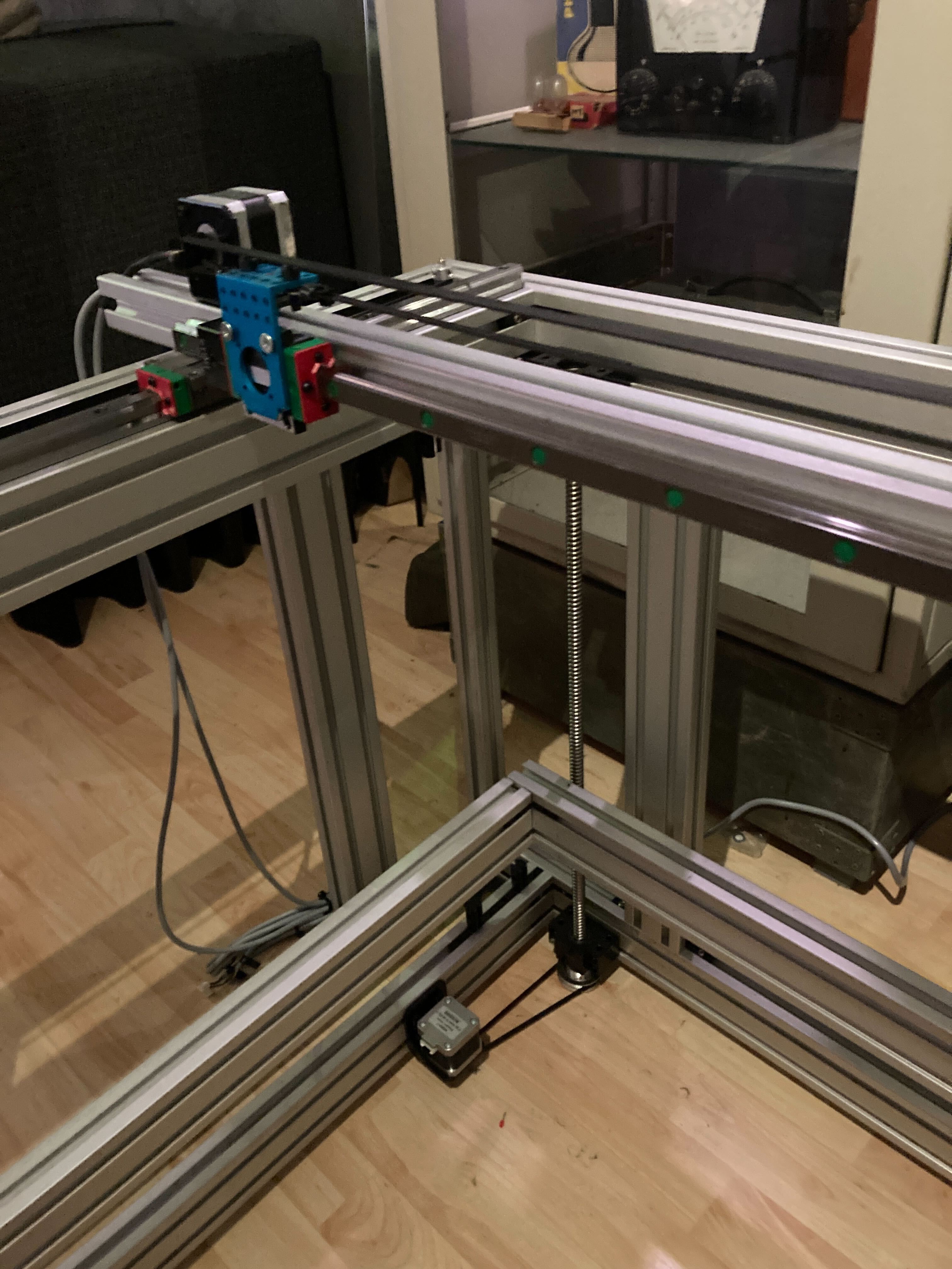
    I improvised a frame out of leftover 3030 / 3060 aluminium extrusion profiles. It measures about 1000 x 800 x 800, and the print volume should be about 600^3.

    I've put 4 motors on the Z axis, which connect to ball screws. They don't have any linear guidance and I'm kind of hoping that for the initial couple of prints (which will have a limited height) it doesn't really matter and the rigidity of the screws near the top to be enough to keep the print bed in place. Each motor is driven by its own controller so that I can do "Z-Tilt" bed calibration in Klipper.

    There are 4 motors on the Y axis, driving 2 QHW15 carriages. They are divided over 2 motor controllers, one for the left side, the other for the right. Each motor controller drives 2 motors connected in parallel. The high amp output of the TMC5160s should be enough to drive 2 motors at a time I hope. Both axes have an end block which will be used for sensorless homing. I'm thinking that I could home both Y axes independently, and use software skew correction for any discrepancies between the locations of the end blocks. If homing the axes independently proves problematic, I will move one of the axis a few mm forward, then home both axes based based on one end block. I will then put the motors in a low amp setting and do a mechanical homing procedure, intentionally stalling for a second while the carriages hit the block (without sensorless homing enabled)


    The 4 Y motors provide enough torque for a slightly heavier X axis, which has 2 motors for the X axis, both connected to a single controller in parallel. The reason I double all my motors is because aligning 2 identical motors is easier than trying to fashion a pulley out of hardware store parts. Usually the pulley constructions need custom 3d or machined parts, which I'm trying to avoid. Also, the axis is balanced, and we spread the load over 2 motors which can both be driven at high amps because of the headroom we have due to using the TMC5160s.

    Technically I can do dual extruders, either mirrored or duplicated, based on whether the carriage is attached to the top of the belt or the bottom of the belt.

    All axes have HIWIN HGR15R rails with QHW15 carriages. They are quite a bit larger and heavier than MGNs... They are also only about 1/3 of the price and meant to be used at this scale. The problem is that they are not really used at this time for printers, so there are no default carriage to NEMA17 mounts or something. Large scale printers at this time are blown up versions of small printers where the MGN makes sense. But I'm not happy paying 250ish per axis at this build volume, when I can get the HGR at 70ish per axis. The carriage is quite cool, it uses ball chains instead of individual balls. I always lose half the balls in an MGN carriage every time I have to replace one, hehe, with the ball chain this is a thing of the past. Finally they are faster and more quiet. We'll have to see how they perform in a 3d printer.

  • The Jonsbo D31 screen

    E/S Pronk04/27/2024 at 22:54 0 comments

    The screen of the D31 case is actually rotated 90%, 800x1280. In order to get it to display upright I had to change my /boot/firmware/cmdline.txt to include:

    fbcon=rotate:3

  • The case

    E/S Pronk04/27/2024 at 21:28 0 comments

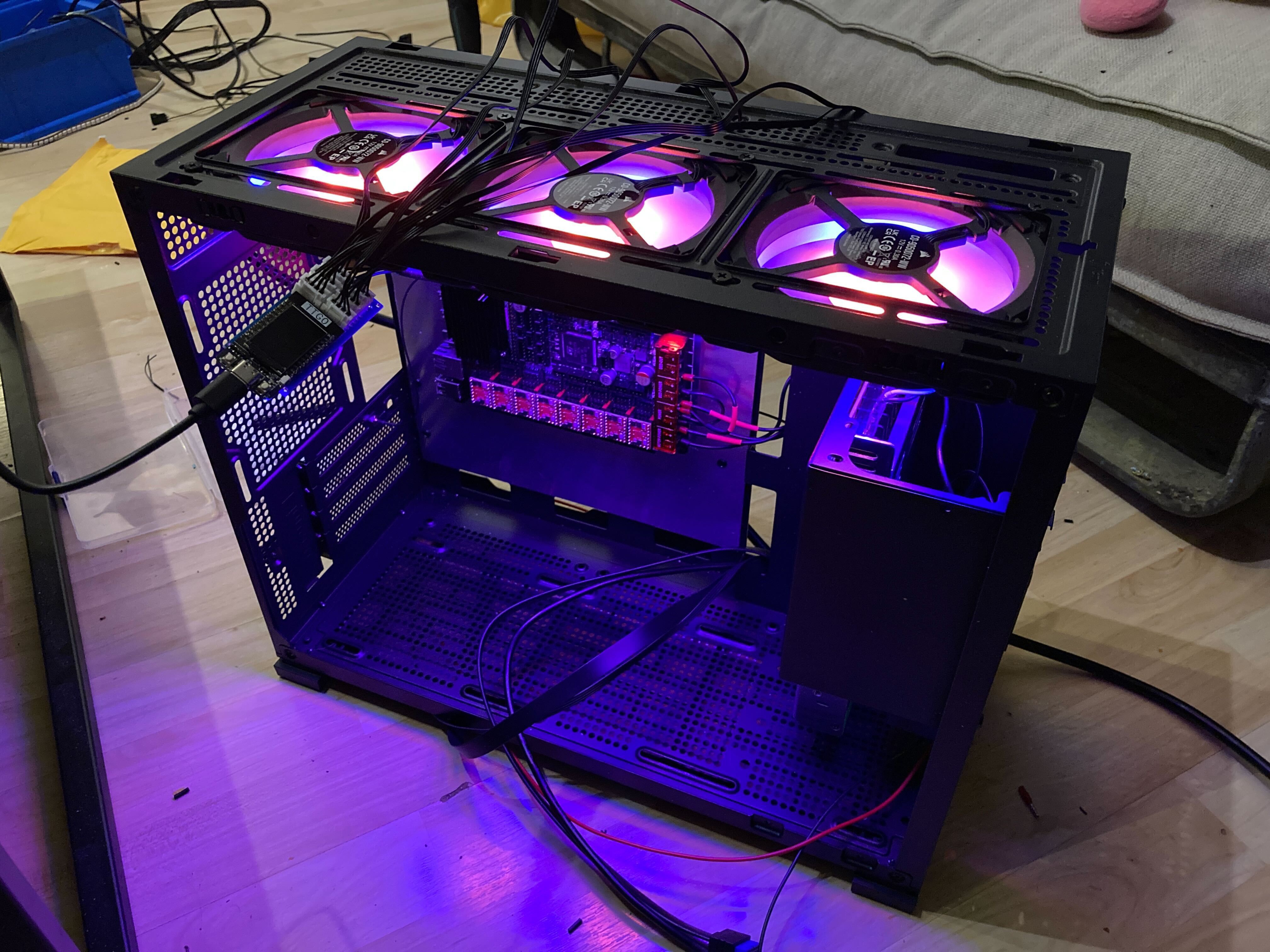
    So without a motherboard the case fans from corsair are pretty useless on their own. But they can just be used as ARGB fans, if you change the pins from the fan. And since we don't have a normal motherboard anyway, and I don't want to waste cycles on ARGB on the printer MCU, I made a small controller out of a spare ESP32 using the RMT driver. 

    I also had to combine the 3 fans into one connector to the printer board, so I had to leave out 2 of the tacho signals. I routed one of the signals to the ESP32 so it can be used to read out the speed using the PCNT driver.  I use this speed to change the colors / animations of the fans.


    The Jonsbo case has a weird little PCIE cover to facilitate the front screen HDMI / USB connections. These just happen to fit the antenna from the CM4 wireless just fine! To mount everything in place I cut a piece of aluminium into the size of a motherboard, drilled some holes and fixed the printer board (and other peripherals that are planned) to the aluminium board. I can then simply remove the "motherboard" as if it is an ATX one.

View all 13 project logs

Enjoy this project?

Share

Discussions

helge wrote 05/02/2024 at 08:48 point

Solid project, love it!

(you're probably adjusting belt tension via the motor mounts. I'll leave a link to my write-up on belt tensioning with a re-purposed hose clamp here for your enjoyment and inspiration: https://hackaday.io/page/7198-hose-clamp-style-gt2-belt-tensioners)

  Are you sure? yes | no

E/S Pronk wrote 05/03/2024 at 16:35 point

Wow, that's a great solution, totally going to use that idea, thanks!!! I was actually exploring belt tensioning at the moment because it seems to affect the stallguard performance, which is acting up.
Currently I'm using "ring crimp connectors" on the ends of my belts, and then attaching those to bolts that tighten the belt when screwed into place, but it has always been troublesome to get it right...
Off to the hardware store!!

  Are you sure? yes | no

Similar Projects

Does this project spark your interest?

Become a member to follow this project and never miss any updates