Got to test out v1.1 of the device on set this week, and it once again worked beyond all expectation. This iteration includes a battery, charger board, and power switch, in addition to some other basic improvements and groundwork for future stuff.
First and foremost, the device is smaller than v1 in every dimension. I've rounded off some more edges to aid with the feeling of a small & portable device, and shaved down any walls that I felt could stand to be thinner. I inset the screws that mount the display to the framework, to make a little more room inside, as well.
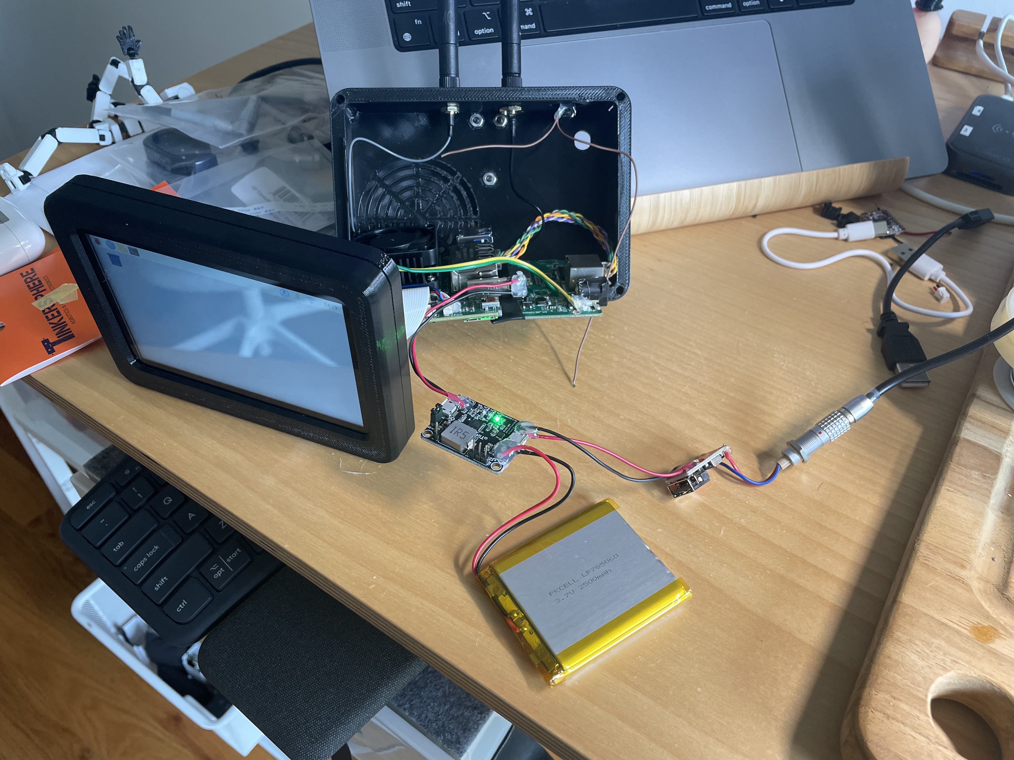
The battery I put in there is an Adafruit 2500 mAh LiPo pack, and the management board is a TinyUPS3.0. I stripped off the battery connector & pins and soldered my connections directly to the board to save space, with good ole hot glue globs to provide strain relief. Haven't had the chance to test runtime on the battery, but it easily lasted half an hour during lunch on set, and I don't really intend to run it on battery power for long stretches of time, anyway.
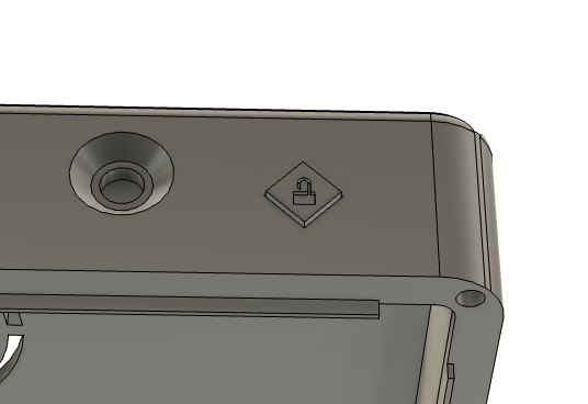
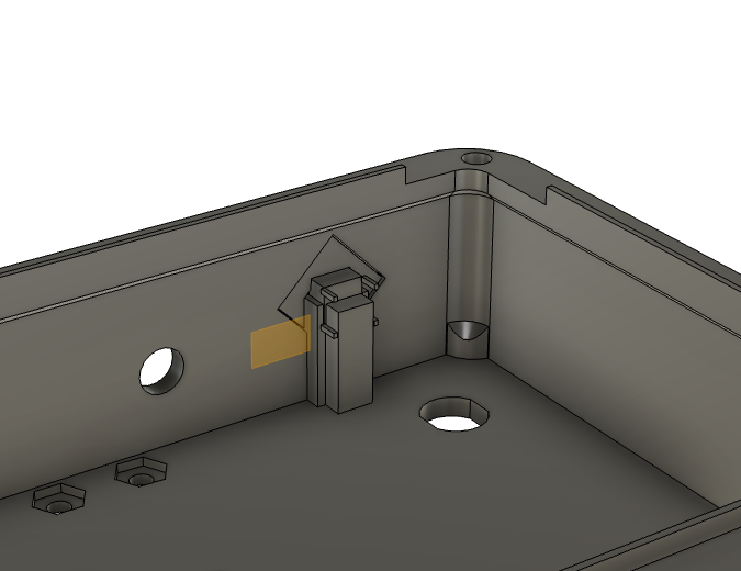
I designed a push-button for the top of the case, the intention being that a short press will lock/unlock the touchscreen, and a long press will initiate shutdown/boot. Currently the button doesn't do anything - I need a reliable way to tell when the rpi is in its powered-down state, but haven't found one yet. My plan had been a sort of latching power switch using a GPIO pin, resistor, and NPN hooked up to the enable pin on the battery management board, but every pin exposed by the rerouter carrier board seems to pull high even when the cm4 is in shutdown. For now I just have a simple on/off switch connected to that pin instead. The Pi is using overlayFS, so unsafe shutdowns should be fine.
I think future iterations will have to use a separate controller (possibly a QT Py, as they're small and I seem to have an abundance of them) to handle that button, so I can have it do whatever I need without relying on the pi GPIO etc.
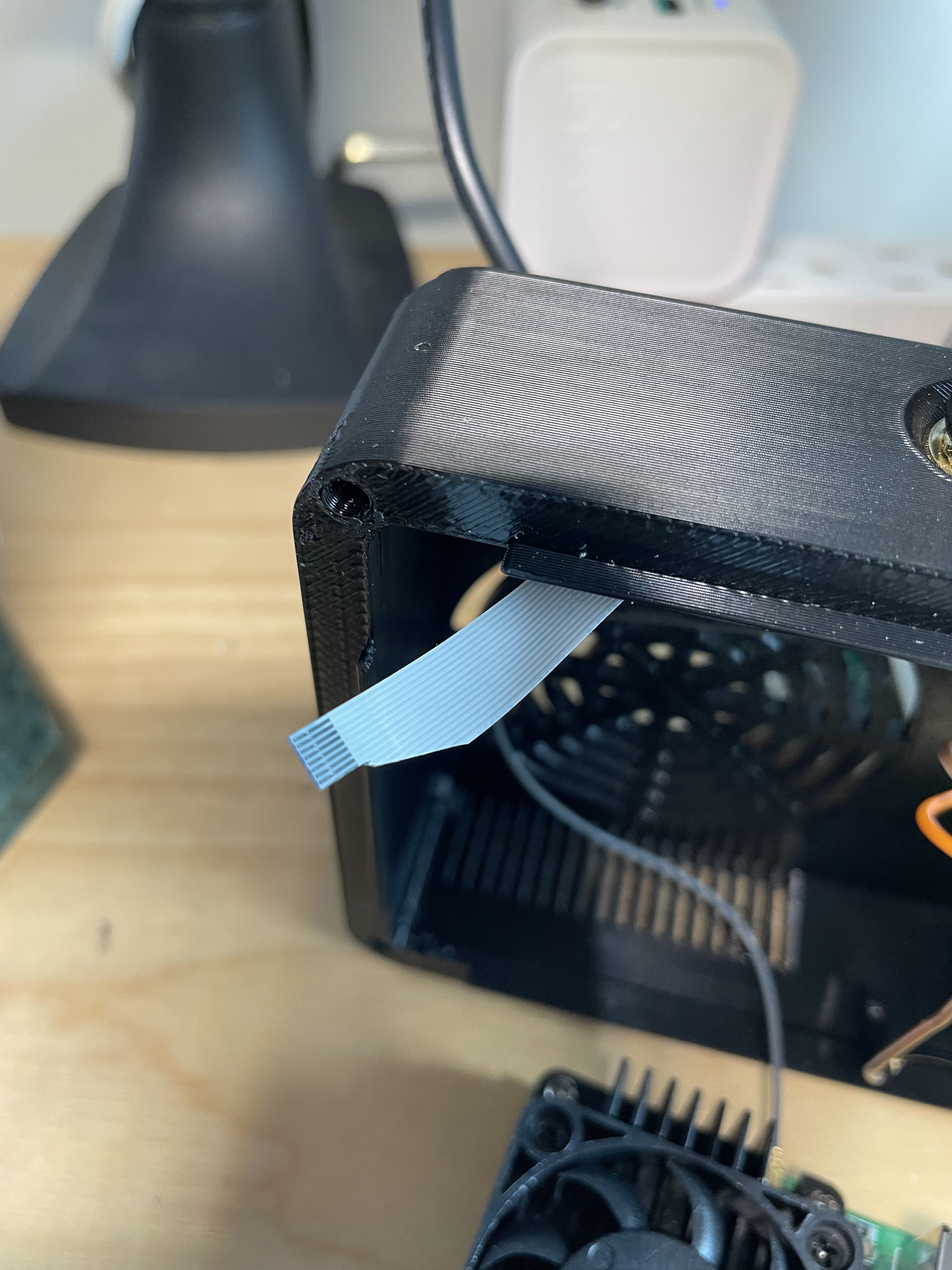
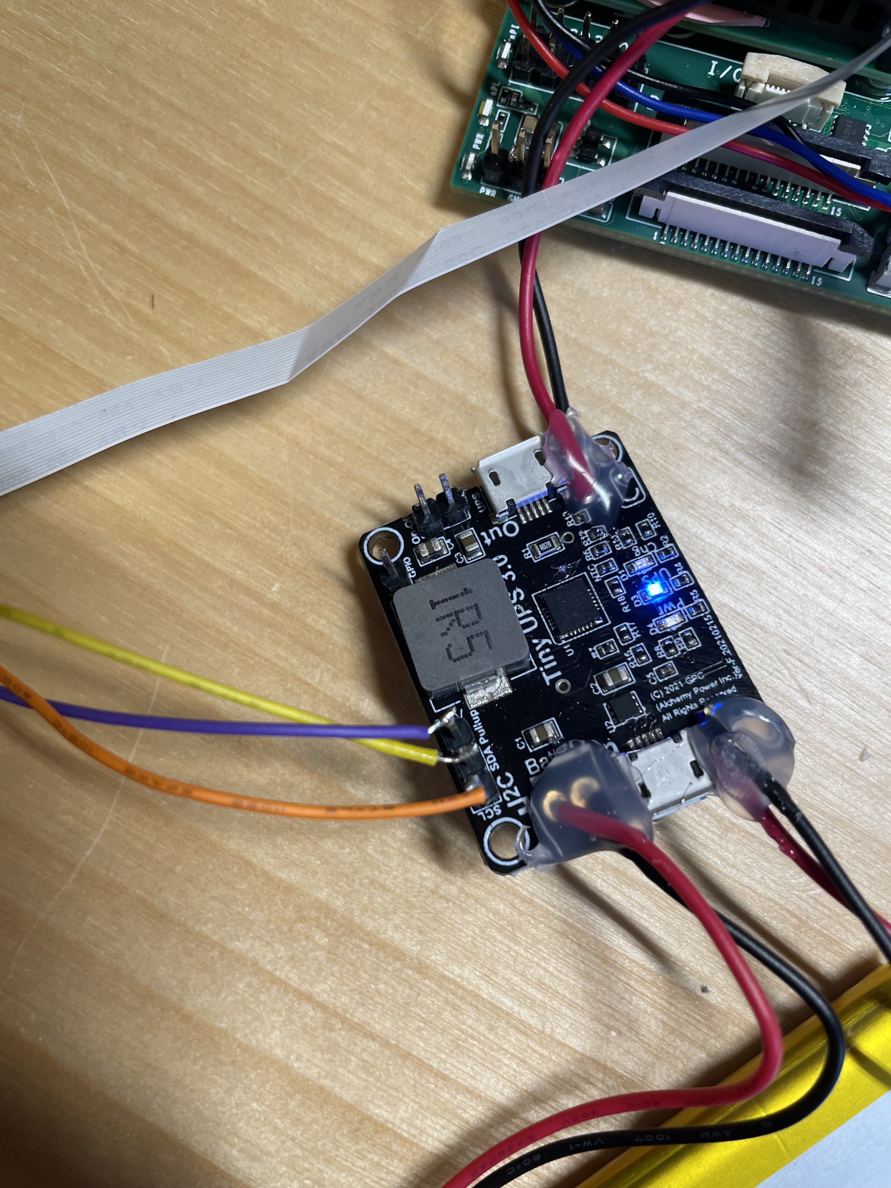
Speaking of, I had to find an 8-pin fpc and breakout board in order to access gpio & i2c on the pi. No problem finding the breakout, but I only had a 15-pin cable at my disposal. Some careful trimming later, and it's working beautifully. Don't trust the pin labeling on the breakout board, however - I did it backwards once before I got i2c communication with the battery board working. But hey, it is working! I can monitor battery voltage etc from a Python script now. Still looking for an elegant solution for graphical battery monitoring, though.
Not strictly related to the device itself, but I also came up with a nice little enclosure for the camera-side transmitter.
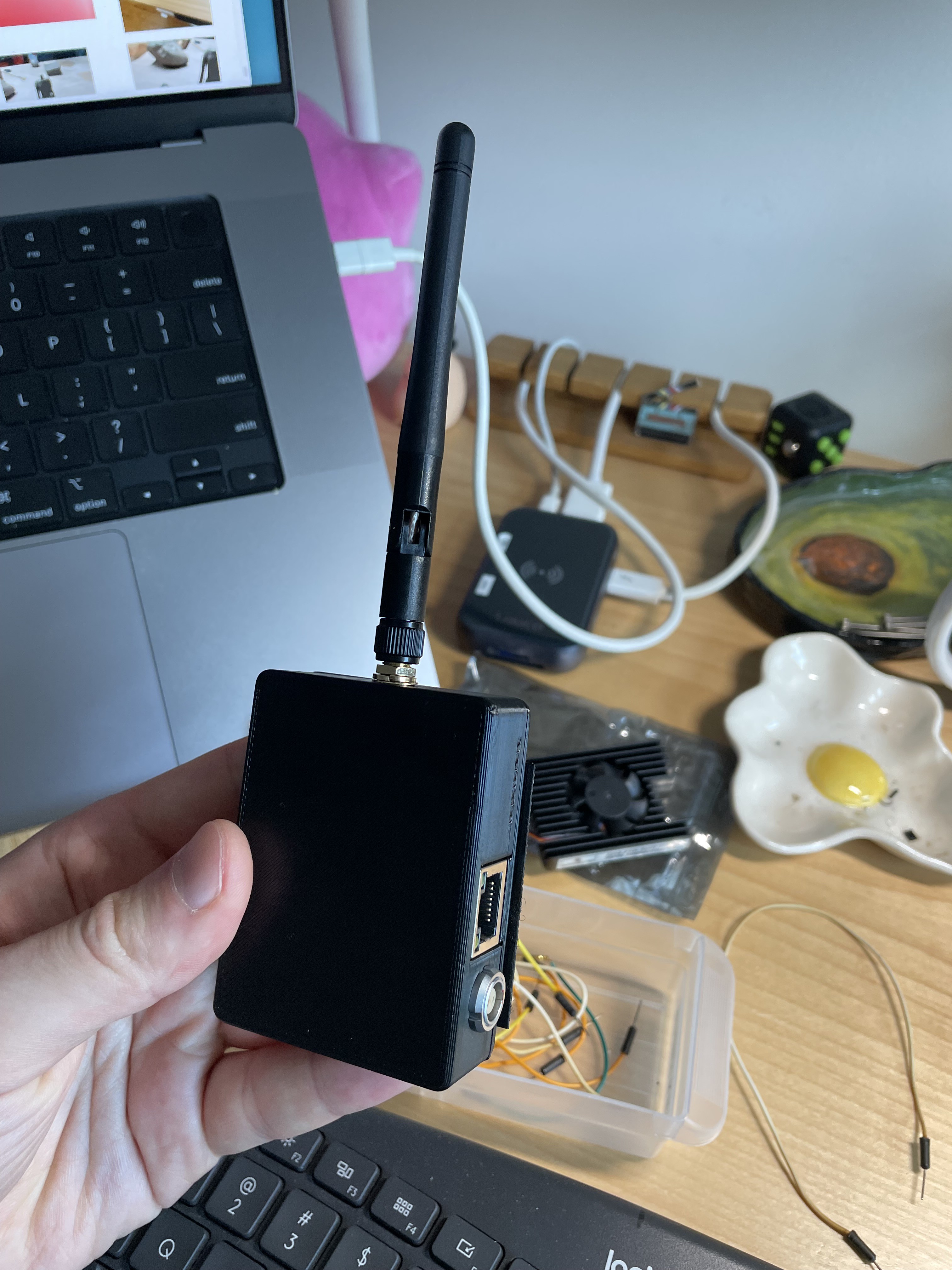
The only real issue with this iteration of the device is that I seem to have fried something on the battery management board - handoff from DC power to battery power doesn't work anymore. The device works fine in both states, but it seems that something on the board gets overloaded and shuts off when it tries to transition from one to the other. Frustrating, as it was working fine until the first test with the case fully closed. I'll have to open it up and take a look soon, though that probably means just buying a new board and being more careful.
 max
max
Discussions
Become a Hackaday.io Member
Create an account to leave a comment. Already have an account? Log In.