I'm thrilled to announce the launch of the CableEnable Labs YouTube channel, where I'll be documenting our journey in creating my game console with a punch screen. The name 'Punch!' captures the essence of punch cards, punches in retro fighting games, punchlines in jokes, and, of course, the physical punches of the screen itself.
Hall Sensors and Initial Setbacks
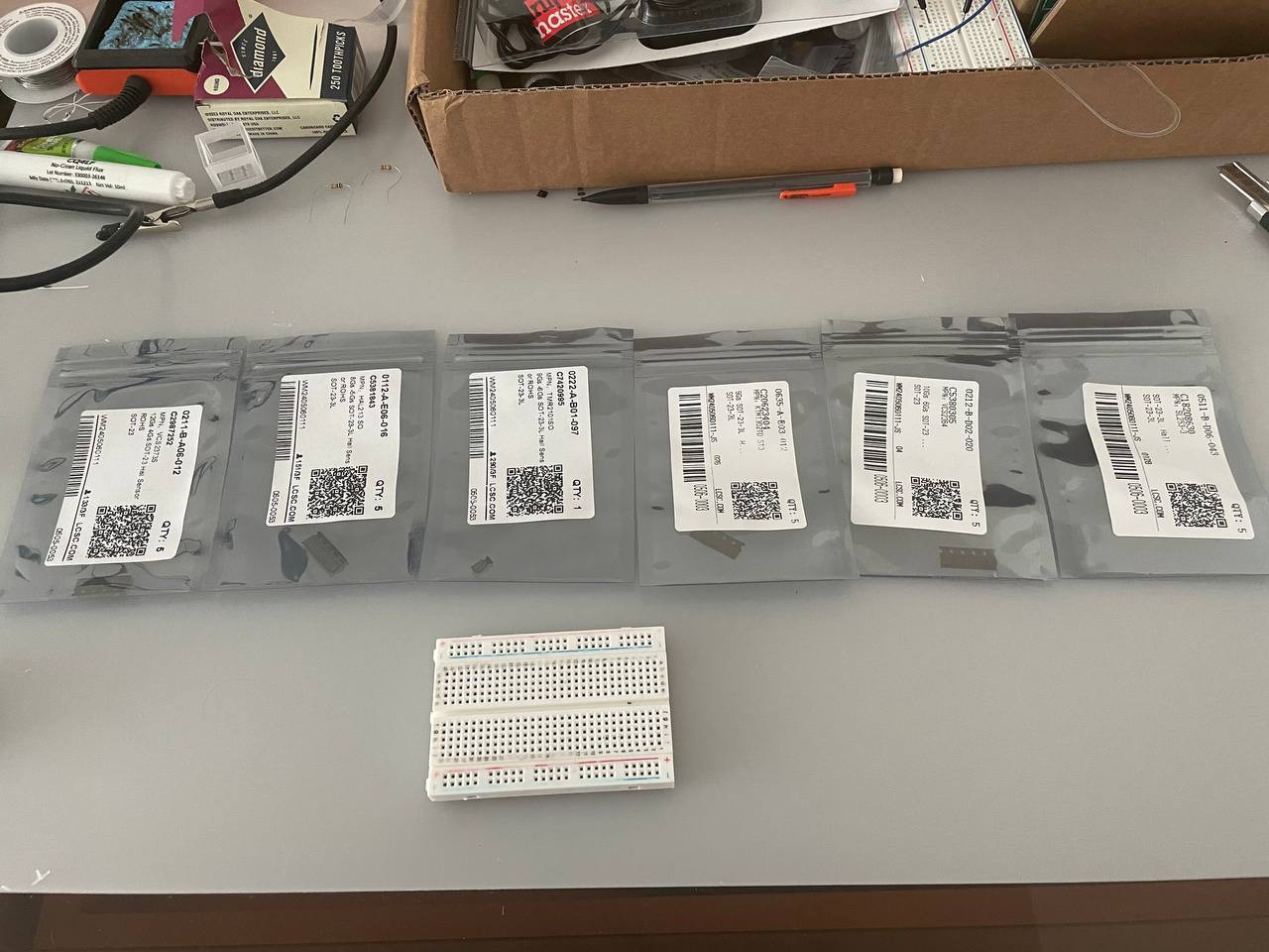
First off, I received some Hall sensors for testing. Unfortunately, I was misled by the numbers on the permanent magnets and ended up with sensors that are too sensitive. Placing them on the other side of the board might cause them to pick up signals from neighboring cells. Despite this setback, the scale is roughly correct, so not all is lost.
Assembling the First PCB
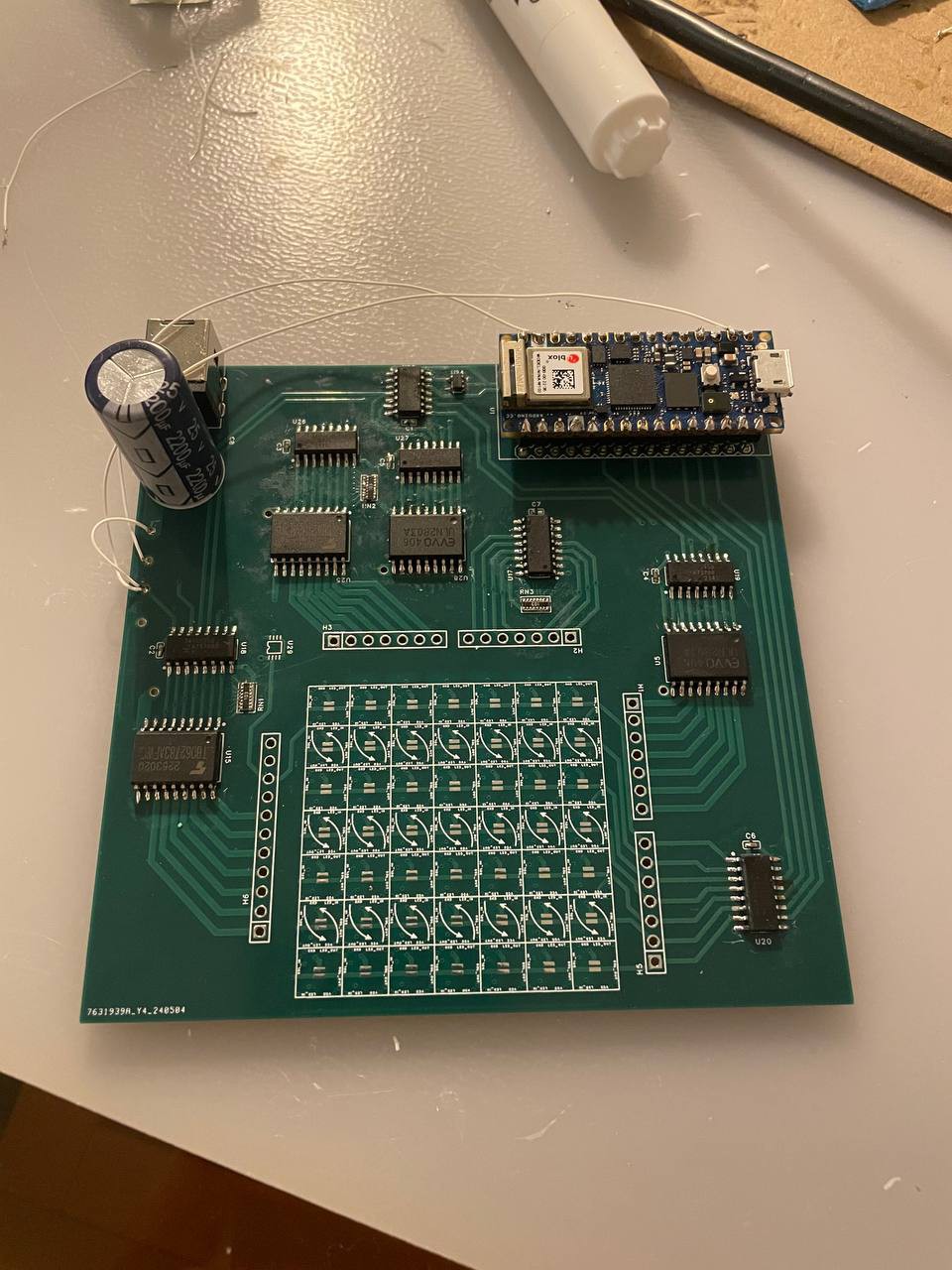
All the components have finally arrived, and I managed to assemble the first version of the PCB. Soldering controllers is surprisingly satisfying—flux really is magic!
Observations and Adjustments
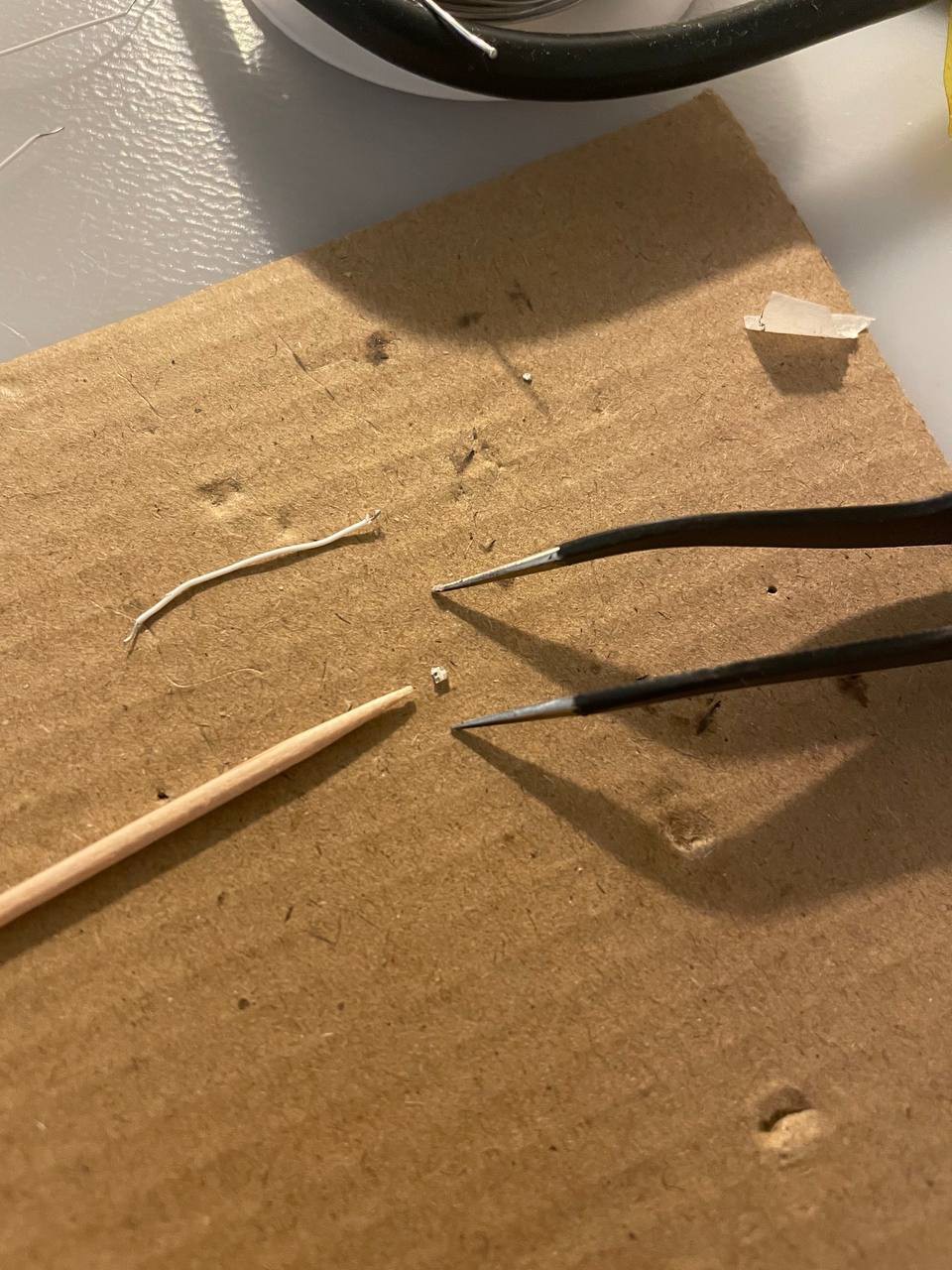
- Diodes: While I could manually solder 1.5x1.5mm diodes, the 1x1mm ones proved too challenging. I’ll be using the PCB assembled on the factory for those.
- Capacitors: SMD 0603 capacitors soldered without any issues.
- Resistor Arrays: The SMD resistor arrays for pull-downs are problematic; I couldn’t tell if they were soldered correctly or if they were shorting the tracks. I’ll likely avoid them in future iterations.
- Solenoid Contacts: I made a mistake with the vias instead of pads for the solenoid contacts, resulting in filled holes that can’t be soldered. This will be fixed in the next iteration, but for now, I’ll test on a makeshift diode matrix.
- Triple Diodes: The triple diodes lacked side markings, requiring me to manually test them before soldering. I've opted for paired diodes with higher current limits for solenoids and single diodes for limit switches in the next version.
It’s Alive!
Despite the hiccups, the basic setup works! A few more takeaways:
- The resistor arrays were indeed poorly soldered and need to be replaced with something more reliable.
- The extra pin for clearing shift registers was confusing during testing and likely unnecessary.
- Using exposed contacts on the board didn’t work as expected for grounding; Hall sensors and buttons are more reliable.
New Components and Testing
The last few weeks have been intense:
- LED Cells: My LED cells from PCBWay arrived and they work! I still need to figure out how to make diffusers for more even lighting and redesign the voxel supports to better accommodate the wires. There was one defective pixel, but luckily I ordered spares.
- Sketching Words: I wrote a small sketch to display words using a 4-bit font (will showcase this later).
Control Scheme and Solenoids
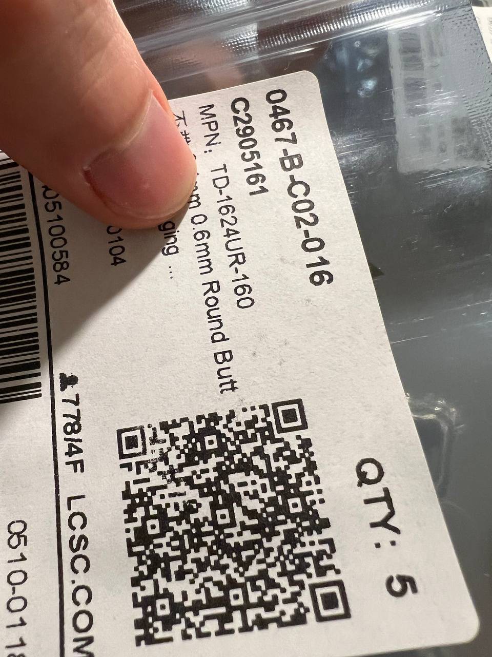
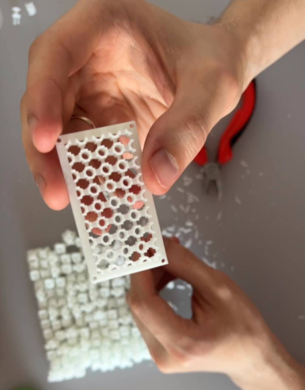
I tested 60 types of limit switches and a dozen Hall sensors, finally selecting the best ones and redesigning the control scheme to include control buttons. This will be sent for printing this week. Additionally, my new solenoids and holders printed well with the SLA printer, needing only minor adjustments for component heights.
New Workspace and YouTube Channel
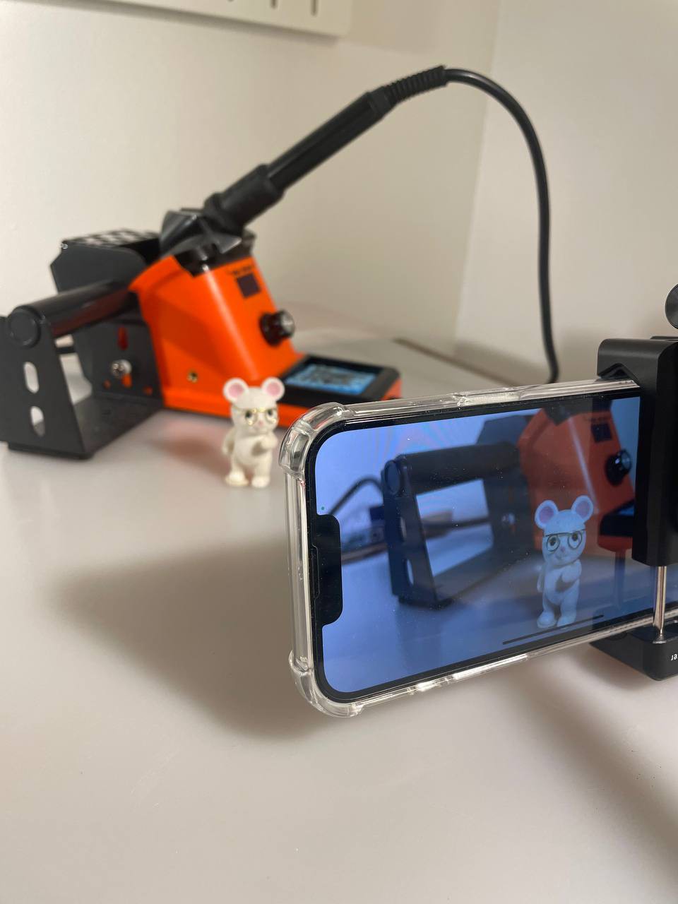
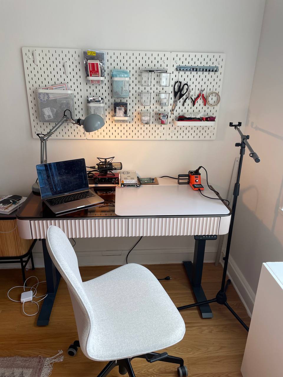
I’ve also set up a proper workspace and filmed the material for our first YouTube video. It will be out soon, and you can expect videos on solenoids and LEDs next. Subscribe to the channel to stay updated!
YouTube Channel: CableEnable Labs
Shoutout to Our Sponsor
A huge thank you to PCBWay for sponsoring the LED PCB print and assembly. Their support has been crucial in moving this project forward. They were super helpful and transparent throughout the ordering and production, so if you need high-quality PCB manufacturing and assembly service, I highly recommend checking out PCBWay!

Stay tuned for more updates, and thank you for your support!
 Dima Matasov
Discussions
Become a Hackaday.io Member
Create an account to leave a comment. Already have an account? Log In.