The final master we shall look at is called the BEEBOP. It is an interesting master since it does not contain a CPU. Instead it interfaces one bus, in this case an Acorn Computers BBC micro’s 6502 bus, to another, the STEbus.
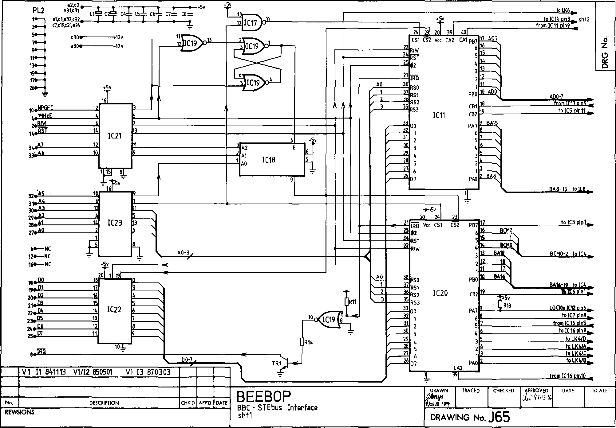
The BBC side of the interface is shown in Figure 6.28(a). The core of the interface is two parallel I/O chips ICs 11 and 20. These chips are 6522 VIAs (Versatile Interface Adaptors). The BBC can write data into these chips, which is used to provide the address and data for STEbus transfers. So that the user doesn’t need to use assembler to communicate at the device level with these chips, a ‘filing system’ ROM was written for the BBC. With such a ROM inserted into the BBC the user can communicate with the STEbus using simple BASIC commands.

Figure 6.28a The BEEBOP, an STEbus to BBC Micro interface.
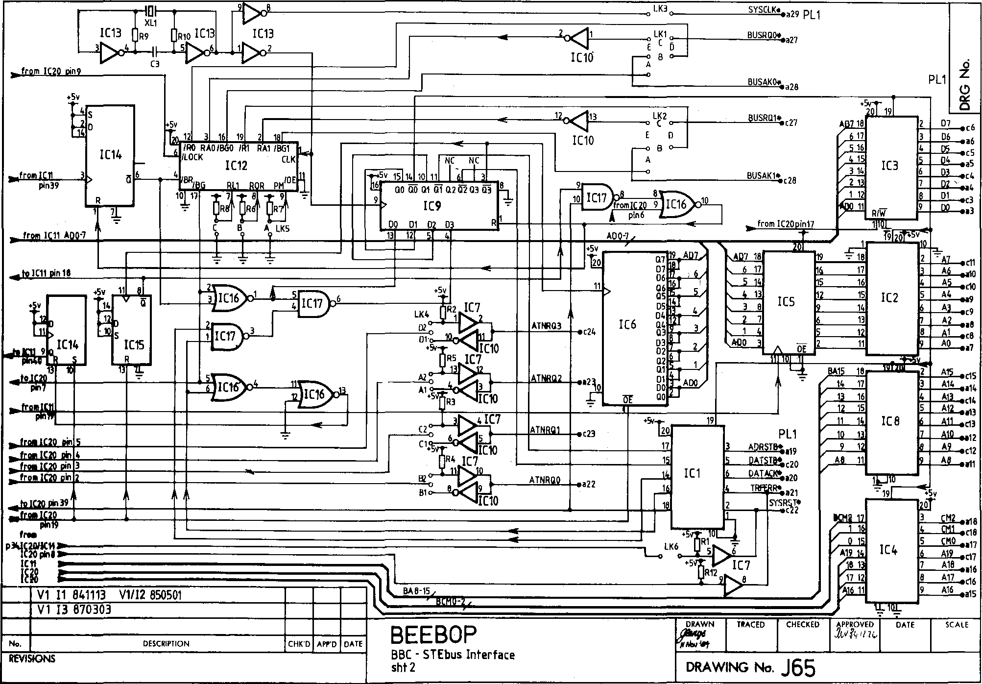
Figure 6.28(b) shows the STEbus side of the interface. Remarkably, apart from IC12 (the arbiter), the whole interface is achieved with no programmable logic at all! A quad flip-flop, IC9, does most of the timings. When /Q0 goes LO it enables the bus driver chips (ICs 3, 2, 8, 1 and 4). ADRSTB*, driven by /Q1, goes LO one cycle after the address and data have been set up. One clock cycle later DATSTB* is asserted. IC5 latches the PB0-7 data bus from IC11, the latch being clocked by CB2 from the VIA (IC11). The data stored in IC5 provides the STEbus address lines A0-7. IC6 latches the data on the STEbus during a read cycle. The data is held by IC6 until it is read at a later time by IC11, which can then transfer its contents to the BBC under software control.
IC13 is the 16 MHz clock circuit, and IC12 the STEbus arbiter, similar to the PAL in Chapter 4. Pins 7, 8 and 9 of the arbiter determine its mode of operation: if it is a potential master what level to request on; whether it is a default master; and whether it keeps requesting the bus until another master wants it (release on request mode). Thus PAL IC12 functions as both an arbiter and a bus requester - this is quite common on STEbus masters. The LOCK signal, when asserted, prevents the arbiter from granting the bus to a second requester, and thus enables the BEEBOP to perform indivisible bus cycles.

Figure 6.28b The BEEBOP, sheet 2.
 Keith
Keith
Discussions
Become a Hackaday.io Member
Create an account to leave a comment. Already have an account? Log In.