 Jesse Farrell
I was using the device for awhile without any capacitance for the downstream ports. When I finally added 120uF to each of the 3x USB ports I was blessed with a symphony of windows device connect/disconnect notifications.
It doesn’t take much effort to theorize the issue. The second the USB load switches are enabled, and the 120uF bulk capacitors are allowed to charge, the host is hit by a tremendous di/dt demand. This could either trip overcurrent at the host, or it might just sag the local 5V rail enough that it resets the device.
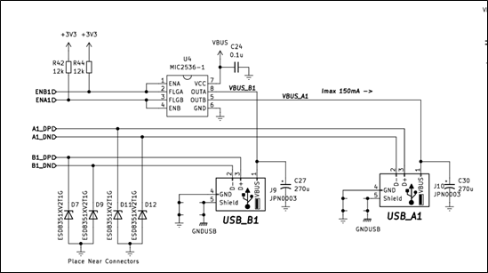
Here’s the critical sections of the circuit WRT this issue. When I first designed the circuit, I read up on the USB protocol, and noticed it called for 120uF for each port… I slapped down 270uF since that’s what I had in my parts bin. I later dropped this down to 120uF when I observed the first connection issue, but the behaviour was unchanged. (foreshadowing - spoilers I should have read the spec more carefully!)
First things first, I had to do some fact finding to understanding this issue better. Here’s a waveform of the general power up sequence.
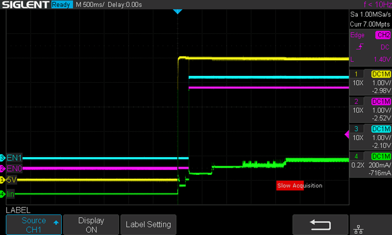
The waveform shows the enable lines (ENB1 and ENA1) from the schematic, external 5V provided by my trusty bench PSU, and the current on the 5V line. Note that when the enable lines are HI, they enable the output of U4 which provides power to the USB devices, hence charging the 120uF caps.
There seems to be two spikes on my current waveform (channel 4 – Green). One which occurs while 5V is ramping, and another that occurs ~200ms afterwords, when the enable is asserted.
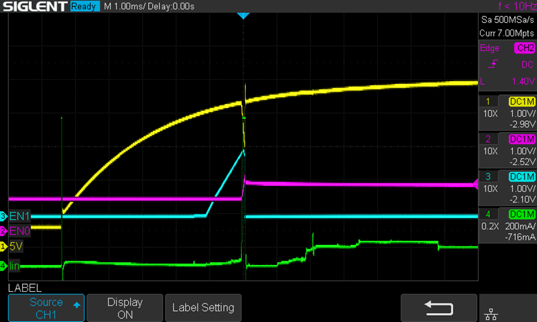
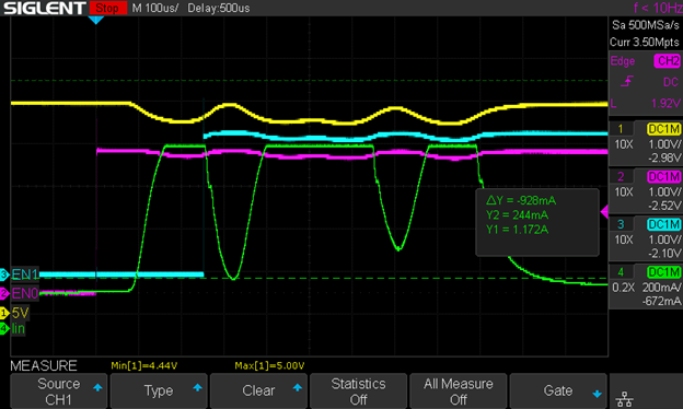
Let’s check the first enable…

Yikes!!! There are actually two pulses that saturate my current sense amplifier (CSA) which is clipped around 850mA. One spike occurs when the device is first connected to power. This is reasonable enough since there’s some significant capacitance on the board. The second spike is more concerning since it seems to be caused by my enable pin floating high and allowing the USB ports to be powered on briefly.
Checking the datasheet for my USB load switches (MIC2536) shows we’re right in the ballpark of their enable thresholds.

I briefly probed the 120uF cap with channel 2 to confirm it was truly being enabled, and yup that cap sure is charging!
I started to toy with ideas relating to the power sequencing of the project. I could (1) delay the 3V3 startup, (2) slow down just the pull-up (PU) voltage somehow with some clever passives, or (3) just remove the damn PU’s entirely.
Idea 3 was easiest to investigate first, and seemed reasonable based on my foggy memory of the LAN95xx chip. That fog was cleared by a quick reference to the datasheet. The LAN95xx does indeed provide its own internal PU, which in theory wouldn’t be applied until it enables itself (hopfully near that 200ms mark we saw earlier).

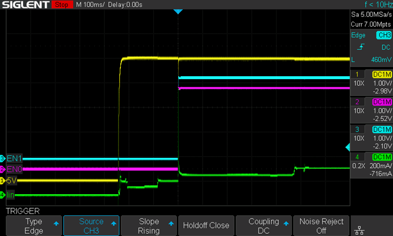
Removing the PU resistors resolved the false trigger issue, see result below. Next up is the massive pulse from the bulk capacitors.
Hindsight is 20/20…. 120uF per HUB!
Here’s a zoomed in look at the massive gulp of energy those 4x 120uF capacitors demand. The current waveform is completely clipped. I expect the true peak current approached 2 or 3 Amps. I did some investigation into different load switches with better current limiting/soft start features, but didn’t find much that fit the bill. Then it hit me…

While designing the board several months ago, I remember thinking 120uF per port seemed ridiculously large, but I sort of shrugged it off. After working on the bug for a little too long I thought I’d better double check the standard. And yup I missed a crucial declarator… its 120uF per HUB minimum! Not per port, Doh!

Now we can safely decrease the capacitance at each port to 47uF. Decreasing the capacitance to 47uF and rebooting yielded the waveform below. It seems like 5V no longer sags to the same extent as before, but the overall current draw is still far too large (once again clipped by my amplifier).

The best solution here would probably be to swap out the load switch mic2536. This device theoretically current limits to 500mA, however we can see above it sure seems like this limit isn’t being applied fast enough. To address the lingering overcurrent issue, I decided I’d add the below circuit across the 5V rail. It will slowly charge during startup, then when the USB power is enabled D1 will turn on and help hold up the rail. Some caveats here though...

This circuit relies on impedance in the power delivery to help sag the rail. If the rail doesn't sag, this circuit will not help. It requires a very low drop Schottky diode to function properly. Sadly, the best thing I had was a 1N5817. Nevertheless I scabbed it onto my circuit to test it out.

And here’s the waveform…
Very interesting. The problem isn’t gone, but its behaviour has definitely changed. I’ll need to buy some better Schottky diodes to evaluate this solution further. I also need to assemble another current sense amplifier for this current range (no more clipped current waveforms!). See you in part 2!
Feb.8.2025 - Fixing the thing
Update, I got some better diodes. My main concern was the forward voltage drop. For the big bulk cap to be enabled so to speak, I need the 5V rail to sag. The amount that 5V sags depends on its source impedance. The only thing I can guarantee WRT the source impedance is that it will at least have a ferrite inline. Beyond this the USB cable length and quality will mostly dictate the impedance.
Based on this I'd like to have the lowest Vfd I can find…. I was looking for something around 0.3Vfd @1A, but honestly something closer to 0.2V or 0.1V would be best (pretty unrealistic!). There were some parts that looked reasonable, but in the end I found some interesting ideal diodes that seemed promising. I've never used an integrated ideal diode, but the spec's were tantalizing enough to give it a shot (Nexperia NID5100). It seemed like a good part to have for future work, so I ordered 100… yes I have a problem.
I made a small perf board circuit w/ the new ideal diode. I probably should have done a test board of just the ideal diode but c'est la vie. It’s the same circuit I shared earlier, just with D1 replaced with the ideal diode.

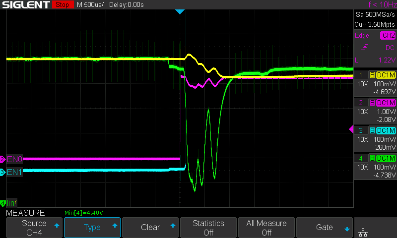
Here's the result.. CH1 (yellow) is the voltage across my bulk caps, and CH4 (green) is the voltage on the 5V rail. It seems like the bulk cap is doing its job and dumping all its stored energy onto the 5V rail during the transition. I'd really like to measure the current waveform being dumped by the bulk cap, but I'm happy enough seeing that the capacitor is discharging (yellow waveform). What's even better is this fixed my windows device connect/disconnect issue
For the next board revision I'll add this circuit, but might tweak the values a bit…. For example I'll probably increase the charge resistor to help reduce inrush current.
Solution added to REV 1.0 errata…
(1) Reduce the port capacitance to 47uF, down from 120uF (likely change to MLCC now)
(2) Add the bulk capacitor circuit
Discussions
Become a Hackaday.io Member
Create an account to leave a comment. Already have an account? Log In.