 Jesse Farrell
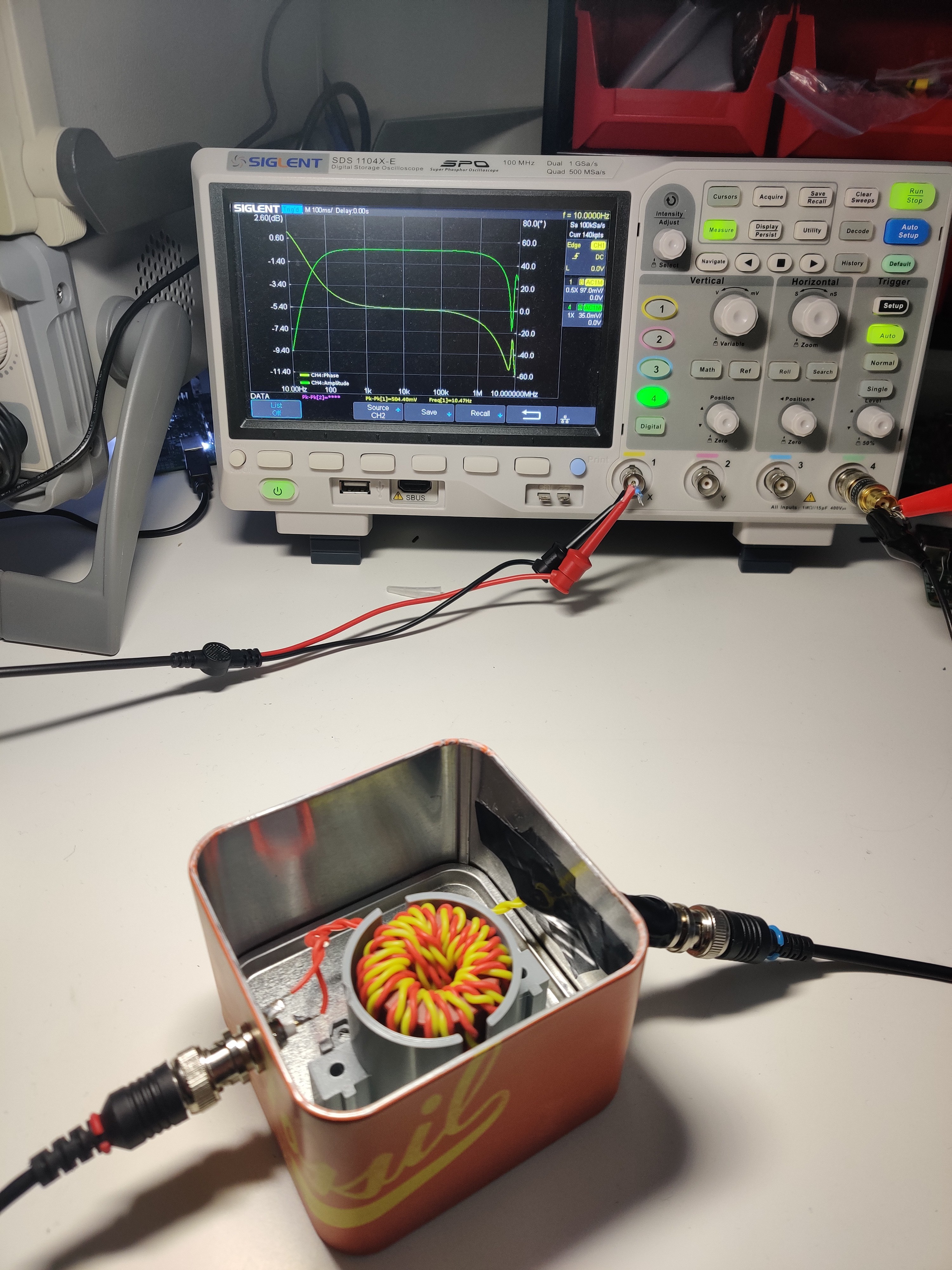
I got side tracked again! This time “designing” an injection transformer to analyze the loop stability of the power supply. No need to reinvent the wheel thanks to Wolfgang Griebel. They posted a DIY injection transformers investigation where they found a core that was extremely comparable to the Omicron b-wit100. The DIY version was named the NVT-1. If you’re considering purchasing an injection transformer, and have a tight budget, I’d highly recommend rolling your own!
FYI - I’m not really concerned about the loop stability of this system. This is just a learning exercise!
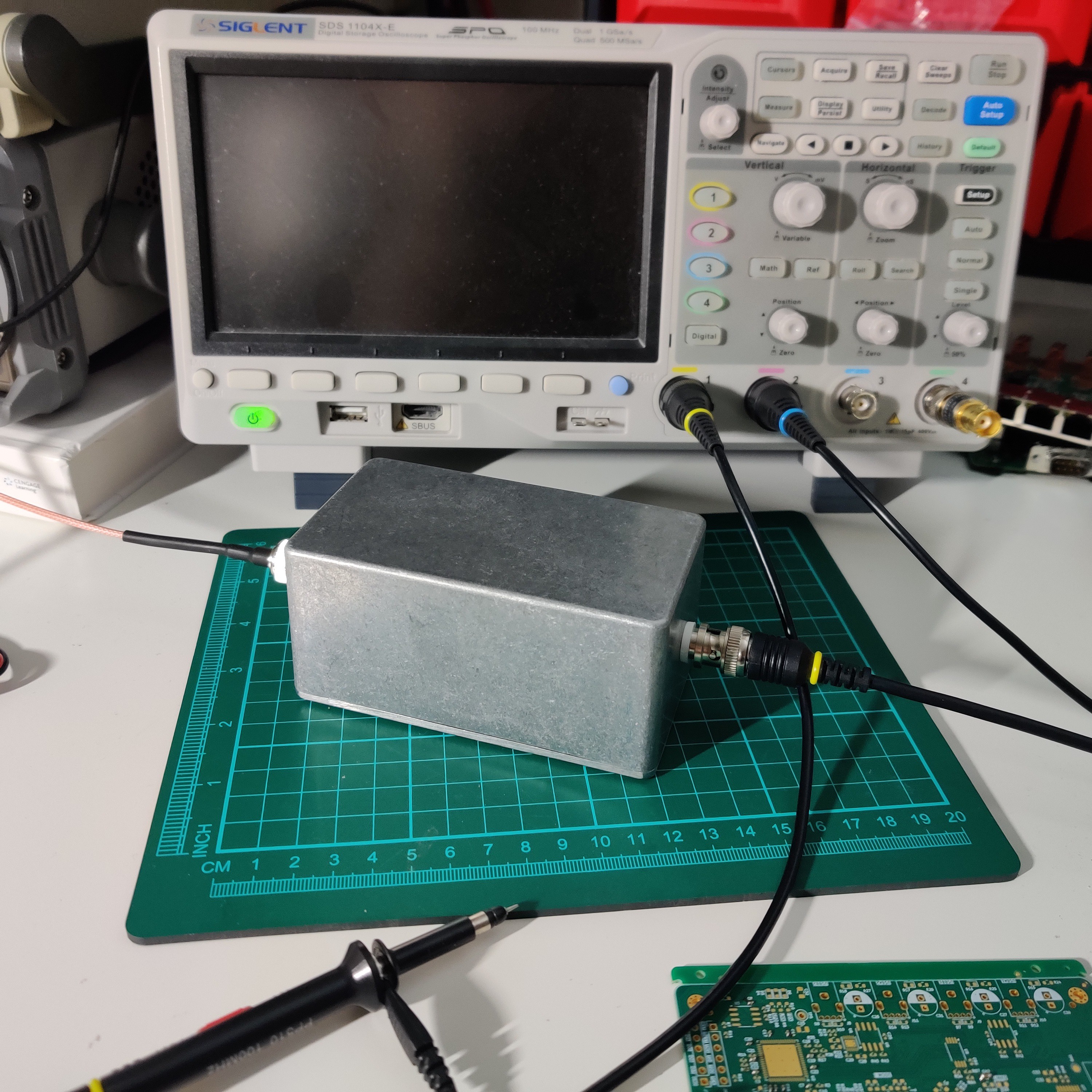
I ended up ordering a better enclosure for the thing, along with an insulated BNC connector to add a bit of polish to the homebrew solution.
Happy with the performance (shown in first image, extremely flat between 100Hz to 1Mz), I moved on to analyze the loop stability of the buck converter on this project. If you’re unfamiliar with loop stability analysis there’s countless papers on the subject. For example; Analog Devices – Understand power supply loop stability, Rohde & Schwarz – Tips and tricks on how to verify control loop stability, Texas Instruments – How to measure the loop transfer function of power supplies, and many more.
I’m going to validate the loop stability by injecting a signal into the feedback network, and observing the outputs response. We can then graph the gain of the signal, as well as the phase shift. From this transfer function we can pinpoint the gain and phase margins, which allows us to make some conclusions regarding the stability of the system. It should also be noted that the response will change based on the systems state. To fully characterize the stability of the system you would need to test all possible operating points. For example, just because the system is stable at 10V wouldn’t guarantee stability at 5V. Even changes in temperature will influence the system. Have a read if your interested in the subject!
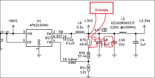
Now that I’ve made an injection transformer, and done some reading, we can turn to the PCBA. I connected the transformer output across R75, and probed either side of the resistor with an oscilloscope (enjoy my paint diagram below). I was somewhat concerned about the downstream components, so I started with a very low-level signal.
The result surprised me! When I first tried to test the system using the above wiring, I saw nothing on the output. I probed pin 4 on U1 and confirmed the injected signal was indeed making its way back to the chip. Eventually I was able to get the output to somewhat follow my injected signal, but it was only when the injected amplitude was uncomfortably large. Furthermore, the output seemed distorted (almost clipping as if it were half rectified).
I ended up blaming the various IC’s on the 3V3 rail for affecting the systems behaviour. So, I got to work soldering a new PCBA, only populating the PSU and various caps scattered around the board.

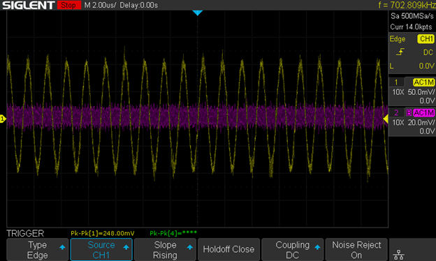
Afterwards I injected the signal again, and was surprised to see the system was mostly unresponsive (see below captures). The injected signal is channel 1 (yellow), and the output is channel 2 (purple). The only way I can influence the output is by using a very low frequency signal.

At this point I realized I’m testing an unloaded system. As a result the switcher is in PFM mode. The expected load on 3V3 for my application is 340mA. Setting the eload to this value, I finally saw the behaviour I expected.
Here’s the system response when injecting a 1kHz 200mVpp signal. Notice the injected signal is much lower than the 200mVpp I expected, yet the output is suspiciously close. It seems like the system is fast enough to compensate the injection. Neat! (and probably expected)

Here’s the system response using a 200mVpp injection signal. If I wanted to cleanup the response, I could use variable injection levels to cleanup the higher frequencies.

Eureka! We’ve characterized the closed loop response for this one operating point!
At 5Vin and 340mA, the gain margin is ~27dB and the phase margin is ~72 degrees.
Side quest complete, stable as a rock!
Discussions
Become a Hackaday.io Member
Create an account to leave a comment. Already have an account? Log In.