 Jesse Farrell
The connection between the USB-ETH controller and the ETH switch doesn’t need to be isolated. Its on the same board with the same reference plane. I’ve included the transformer for now as a failsafe, but there’s a network of DNP’d parts on the backside of the PCB that will hopefully replace the transformer in REV01 (cost savings!).
There are several application notes that outline transformerless PHY-PHY communication, but the exact implementation depends on the line-driver topology, and seems pretty silicon dependent. A good overview of the two line-driver topologies is provided in ENT-AN0106. The main takeaway are the two images shown below.

So how can we accomplish this without the transformer? There’s no reference design or app-note for my specific devices, so I’m going to need to do some research to better understand the topic. Based on the termination of the devices I believe LAN9512 uses a current-mode line driver, whereas I1P75G uses a voltage-mode line driver. Linked below are several app-notes I read to help design the interconnect.
AN2190 - Transformerless Applications of Microchip’s Ethernet Devices (Current-Mode)
TLK110 - Ethernet PHY Transformerless Operation (Current-Mode)
RTL8305SC – Single Chip 5Port 10/100MBPS Switch Controller (Current-Mode)
ANLAN120 – Capacitive Coupling Ethernet Transceivers without Using Transformers (Both Modes)
ADI WIKI - ADIN1300 and ADIN1200 with Capacitive Coupling (Voltage-Mode)
SNLA088A - AN1519 DP83848 PHYTER Transformerless Ethernet Operation (Current-Mode)
Interfacing Intel® 8255x Fast Ethernet Controllers without Magnetics (Current-Mode)
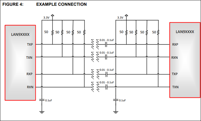
Maybe I was worried for nothing, the transformerless design looks suspiciously simple... In nearly every document the transformerless application is just a coupling capacitor placed in the signal path b/w the two PHY s. See example below from AN2190 (Current-Mode).
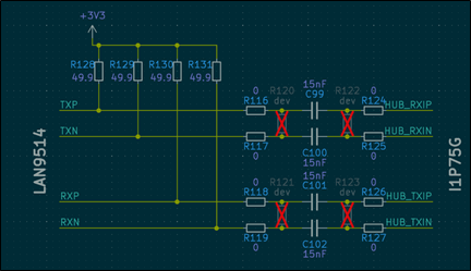
Shown below is the existing biasing network for the current-mode line driver (LAN9512). Based on everything I’ve read I should just be able to remove the magnetics along with its supporting CT bias, and couple each data lines with a >15nF capacitor.

On the voltage-mode side. I believe I’m able to directly connect each line to the coupling caps, since (I recently discovered) the device is internally biased. The final network is shown below.
Oh boy does this not work. Probing the voltage-mode side (I1P75G), it seems like the bus is floating. It periodically droops down to GND, then shoot back to VCC. I was able to get the link working but I’m still not happy with it… will discuss my solution in the next post.
Discussions
Become a Hackaday.io Member
Create an account to leave a comment. Already have an account? Log In.