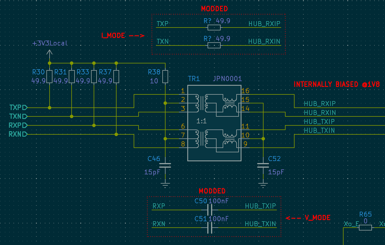
I was able to get the connection between the two PHY’s working, but more tuning is needed. As it stands, these are all just “eye-balled” values, and that really doesn’t sit well with me. What I really need to do is read the 10BASE-T and 100BASE-TX standards to better understand the underlying protocol. Even understanding the protocol, I still don’t know the exact architecture of either PHY. Nevertheless, I’ll post the results I have so far to document the journey.
I’ve collected some A/B comparisons for the transformer (xfrm) and xfrm-less solutions. The control uses a Pulse H1102NL, and the xfrm-less solution uses either a resistor or capacitor in its place.

So first let’s look at the change to TXP/TXN shown above. This signal is driven by LAN9514 (Current-Mode), and the MOD was a small series resistor. The main thing I noticed is a shift to the peak-peak value, and the dc-offset of the signal. I’m impressed how well it handled this change in impedance.

That was the sending end, now let’s see what’s received by I1P75G (net HUB_RXIP/N above). Its okay, though somewhat overly attenuated. I suspect some tweaking would be beneficial here!

Next, we’ll look at the data on the sending end of voltage-mode driver (I1P75G). The MOD here was a pair of 100nF coupling caps.
I believe the ringing on the STOCK circuit can be explained as follows; When both HUB_TXIP(N) are equal then there won’t be any current flowing into the windings of the xfrm and it appears high impedance to the driver. Moreover, any small amount of current that is conducted through the center-tap and its small capacitor would be impeded by the common mode choke. Both these factors effect the load impedance seen by our voltage-mode line driver.

Lastly is the received signal at LAN9514. The signal looks great, but the DC offset is in need of some attention. The received signal is biased to 3V3, as a result the AC coupled signal rides on-top 3V3 and throws it up/down by 500mV. As a result, I’m likely overstressing the LAN9514 receiver.

Transmission Line – Realization
After stressing about the termination of the signal for longer than I care to admit, I came to the realization that its not particularly critical here. The rise times are ~3ns, so the frequency is approx. 117MHz (0.35/3). In FR4 that frequency has a wavelength of ~1.208meters. So the critical length would be about 60mm (λ/20), depending on who you ask.
I’ll keep this in mind for my next round of changes. Atleast the link b/w my two PHY's is stable now!
 Jesse Farrell
Discussions
Become a Hackaday.io Member
Create an account to leave a comment. Already have an account? Log In.