[Cover illustration based on icons by Freepik and Natthapong on Flaticon.]
Basic IO port configuration
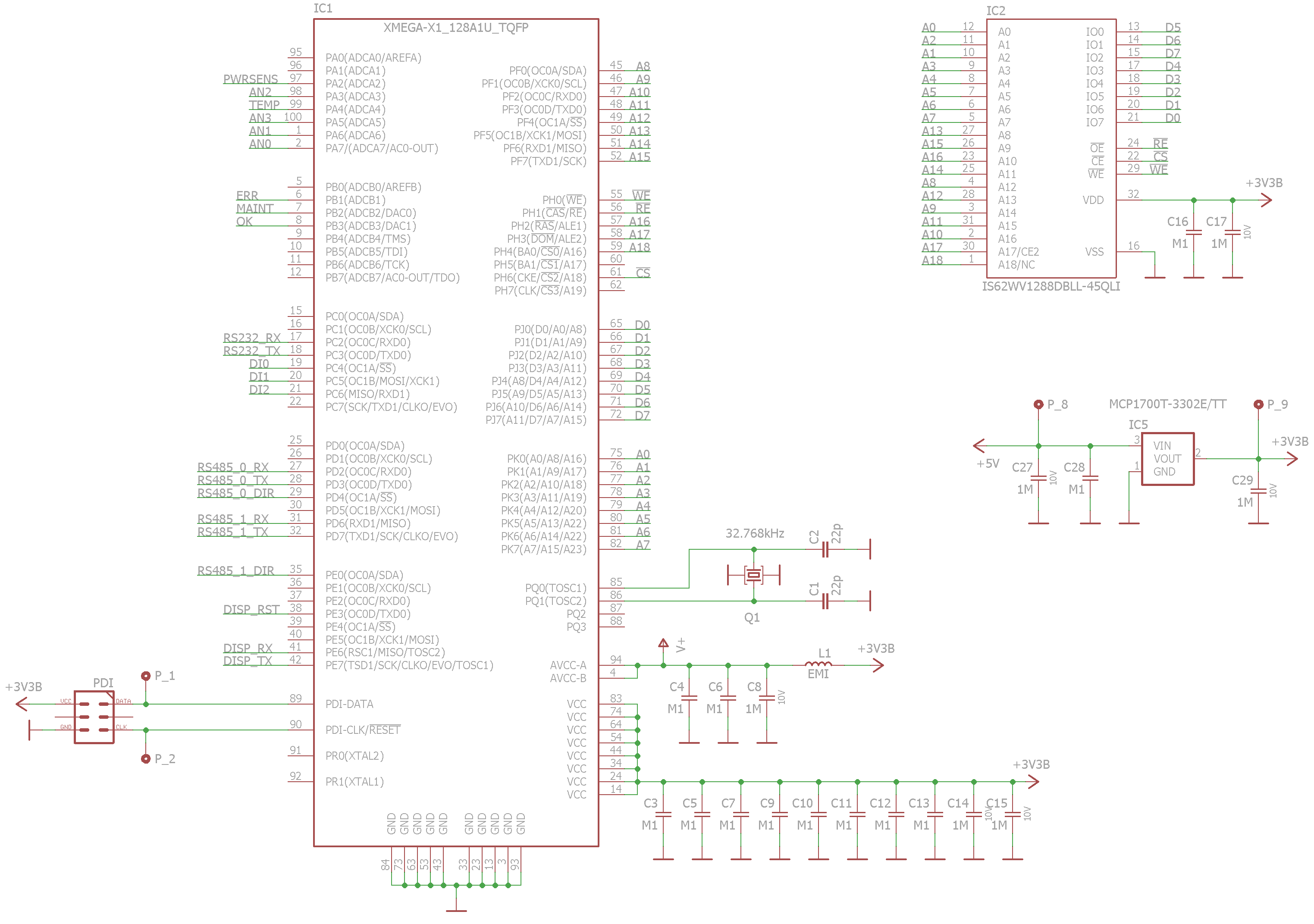
EBI port   IO port name   Function
 3            PORTF        address bus (15:8)
 2            PORTK        address bus (7:0)
 1            PORTJ        data bus
 0            PORTH        control signals, address bus (21:16)
(Pinout: see XMEGA AU Manual > EBI > I/O Pin and Pin-out Configuration > SRAM 4PORT NOALE)
Note: In the A1s the EBI doesn't have the PORT3, so you cannot use them in NOALE mode. Only A1Us have the PORT3.
I used this very basic configuration for this project.
Schematic

How to use external RAM in C
The compiler can automatically and seamlessly place variables in the external RAM if it immediately follows the internal RAM. But: watch the stack. The stack is by default placed at the end of the internal RAM. Further reading on memory sections and stack: http://www.nongnu.org/avr-libc/user-manual/malloc.html
Init code example
void external_ram_init(void) __attribute__ ((naked, used, section (".init1")));
void external_ram_init(void)
{
  // clear r1
  // Needed because this is in the .init1 section

  asm volatile ("clr  __zero_reg__   \n\t");

  // set IO pins

  PORTF.DIR = 0xFF;  // EBI A15-A8
  PORTK.DIR = 0xFF;  // EBI A7-A0
  PORTH.DIR = 0xFF;  // EBI A18-16, CS, RE, WE
  PORTH.OUT = _BV(0) | _BV(1) | _BV(6) | _BV(3);   // EBI: RE, WE, CS: active low signals (idle is high), CS2: active high (not used but connected -> activate)

  // set EBI port configuration

  PORTCFG.EBIOUT = PORTCFG_EBIADROUT_PF_gc | PORTCFG_EBICSOUT_PH_gc;
  EBI.CTRL = EBI_SRMODE_NOALE_gc | EBI_IFMODE_4PORT_gc;

  // set the chip select 2 for the SRAM

  // Note: I didn't want to use the CS3 because if it's used alone (no other CSs) then no CS signal is emitted. See
  // see XMEGA AU Manual > EBI > Chip Select as Address Line. I needed the CS signal because the SRAM chip had lower
  // current consumption with inactive CS (idle mode).

  EBI.CS2.BASEADDR = 0x0000;
  EBI.CS2.CTRLB = EBI_CS_SRWS_1CLK_gc; // 62,5ns R/W cycle @ 32MHz - you have to meet the SRAM speed specification (see the SRAM datasheet)
  EBI.CS2.CTRLA = EBI_CS_ASPACE_128KB_gc | EBI_CS_MODE_SRAM_gc;
}
Here the external RAM is placed to the range 0x0000 - 0x1FFFF. The IO registers and the internal RAM have priority over EBI, so effectively only the 0x4000-0x1FFFF range is used here.
You need to put this code in .init1 because .init2 initializes the stack. If your stack is in the internal RAM, you can put this to the .init3 (the .data and .bss sections are initialized in the .init4 section) (http://www.nongnu.org/avr-libc/user-manual/mem_sections.html). Also the r1 register is initialized in .init2, so in .init1 it is a good idea (I think) to clear it manually.
Atmel Studio hack for ext. RAM debuggings
Open c:\Program Files (x86)\Atmel\Studio\7.0\packs\atmel\XMEGAA_DFP\1.0.36\atdf\ATxmega128A1U.atdf
Add the EXTERNAL_RAM line like this:
<address-space name="data" id="data" start="0x0000" size="0x1000000" endianness="little">
    <memory-segment start="0x0000" size="0x001000" type="io" rw="RW" exec="0" name="IO"/>
    <memory-segment start="0x1000" size="0x000800" type="eeprom" rw="RW" exec="0" name="MAPPED_EEPROM"/>
    <memory-segment start="0x2000" size="0x002000" type="ram" rw="RW" exec="0" name="INTERNAL_SRAM"/>
    <memory-segment start="0x4000" size="0x00C000" type="ram" rw="RW" exec="0" name="EXTERNAL_RAM"/>
  </address-space>
Restart.
This will show you the range 0x4000 - 0xFFFF (external RAM) in the memory window during debugging, also the variables in the external RAM will be showed correctly when hovering the variable names. You can edit the size if you need.
Unfortunately you can't configure this on a project basis (I think), so you'll have to watch yourself whether the RAM was exhausted. Alternatively you could create separate .atdf files for each project with different RAM sizes/ranges.
How to place variables explicitly in the internal RAM
If you need some data security in your...
Read more » Gabriel Cséfalvay
 Jac Goudsmit
 EtchedPixels
 teardownit