So, I joined the GPSDO bandwagon....
There exist multiple designs, with various ways to implement closed-loop control - from simple jellybean logic gates, through microcontrollers (Arduino, STM32, ARM MCU, etc.), and various FPGA/CLPD implementation for sub 1ns accuracy.
I started with the James R Miller's EXOR phase detector based approach as I already had 10kHz reference source. It was obvious to follow that route, and add some NMEA monitor to just indicate what is the quality of the reference signal. Just throw some jelly beans 74' with 1/1000 divider, some extra analogue circuitry to filter out the feedback control signal. The phase detector that I initially planned to use was either an EXOR that fixes a phase difference of 90 degrees between reference and VCO derived 10kHz, or bang-bang phase detector that can hold both signals in sync. The choice of 4046 was obvious as it offers an alternative and phase detector can be selected with just a jumper in a prototype board.
but...
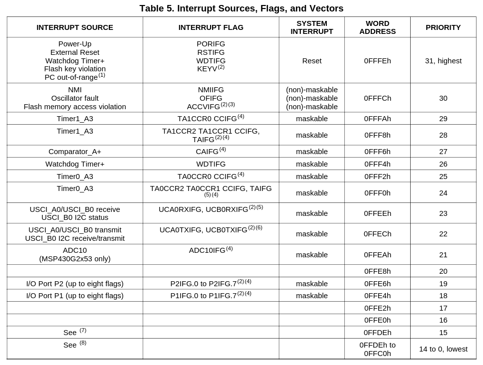
Once the GPS fix status indicator (with SPI LCD) was ready I realized that the msp430g2553 which I employed for that task, had free counters (timers) that might be used for something useful.
Such as produce a nice metric for lock quality indicator, etc. I connected them to the 10kHz reference signal as well as to the VCO divided 10kHz, and compared them.
With the capture sampling frequency of DCO over-clocked to 20MHz the resolution of half period of 10MHz signal can be reached.
I do realize that the internal DCO oscillator has a very low stability, but since both,
reference and generator signal are compared against the very same decimation clock, the error cancels out (on that later).
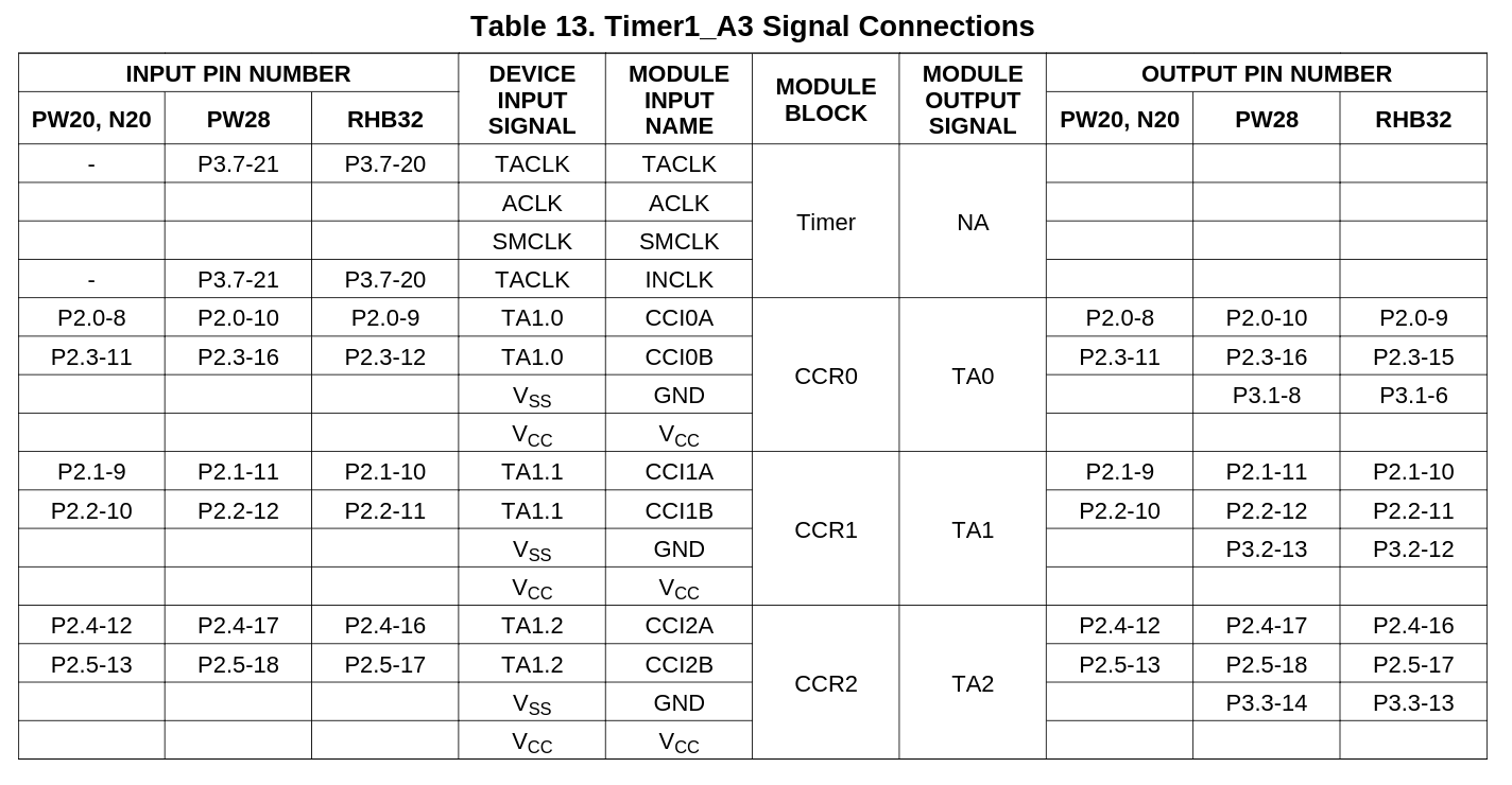
Timer1 has three (or two - depending on how crippled you treat the CCR0 one) capture/comparator modules that can be used to capture flanks of two independent signals.
Table 13 from (https://www.ti.com/lit/ds/symlink/msp430g2553.pdf
Both modules (CCR1 and CCR2) produce interrupts, and their handlers can help measure mutual phase difference between said flanks.
The phase difference between rising edges of these two signals becomes the error function. Treat it as the input to a simple PID controller, and close the control loop with PWM generated signal to influence VCO generator. To generate it the third counter of the very same timer CCR0 is used - not through comparator output but with the use of ISR routine. Simple as that, but still accurately and jitter-free, as the priority of this ISR is the highest.

The PWM generated control signal filtered through low-pass filter.
With 20MHz SMCLK and 16 bit counter length, the PWM frequency is quite low, but still reasonable for RC op-amp based 1-order filter.
That would be it if I wanted to produce 10MHz only, but what else can a tiny 16-bit controller with just 512 bytes of memory can do?
It turned up it can quite a lot, given the amount of available peripheral, even with a pin assignment limitations.
To sum-up:
- P1.1/P1.2 RX/TX pair to communicate with GPS - not only receive and parse GGA/RMC NMEA messages, but during boot also configure and reset the GPS module. The extra use of the TX line, aside of boot-up reset/configuration, it is used for debugging/status output - with format of frames intentionally incomprehensible by GPS module). By synchronizing the output with the GPS message per second framing, it can be merged to produce a common serial output 4800bps. My goal was not to support _ANY_ GPS module, I focused on the messages and features supported by a particular model (Rockwell Jupiter TU30-D140) - for any other module certain changes would be required, but not impossible to implement.
- hardware SPI to communicate with PCD8544 LCD module. Display real-estate is not big, but sufficient to display status of the control loop and readiness of the 10MHz output, and suitability for the purpose...
 sq7bti