 TJ
TJThe component reduction revolved around the band pass filter. Removed that LM358 and used the extra op-amps from the bass and treble sections.
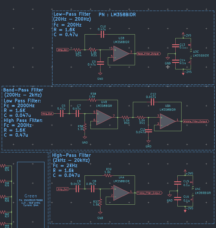
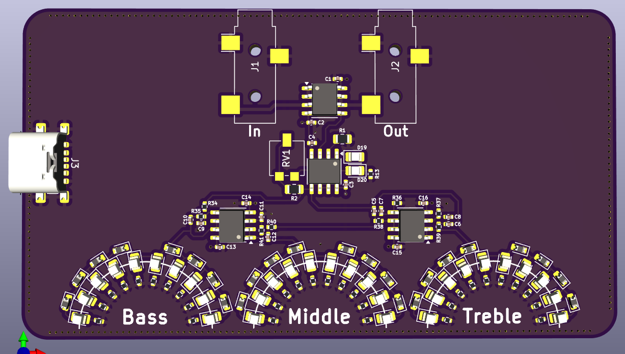
After getting the schematic staightend out. Worked on re-laying out the filter sections. I'm a bit happier with the layout of the filter section. It's kinda starting to look like a dude at a turn table or that one boss from FF7.
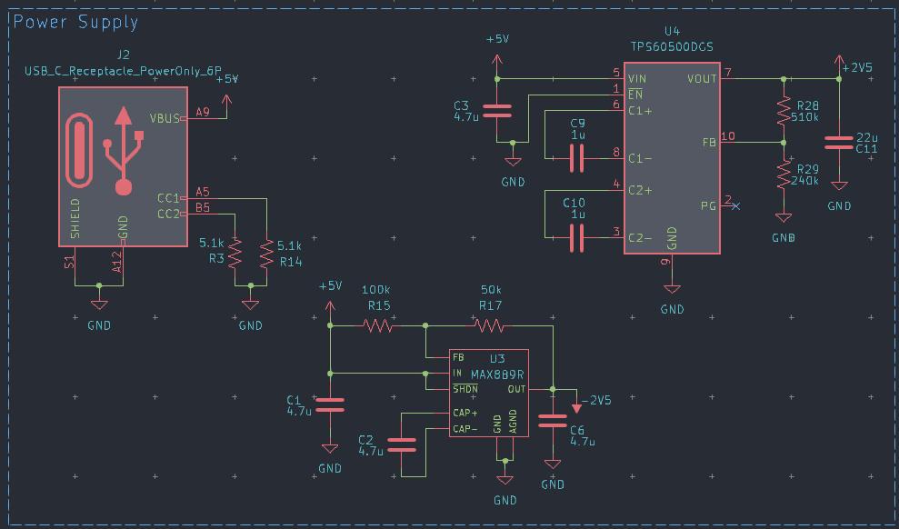
Designed the power supply circuit around the MAX889R and the TPS60500 for the dual rails. Both are capacitor based switching regulators. The input power is coming in from a USB C PD connector.
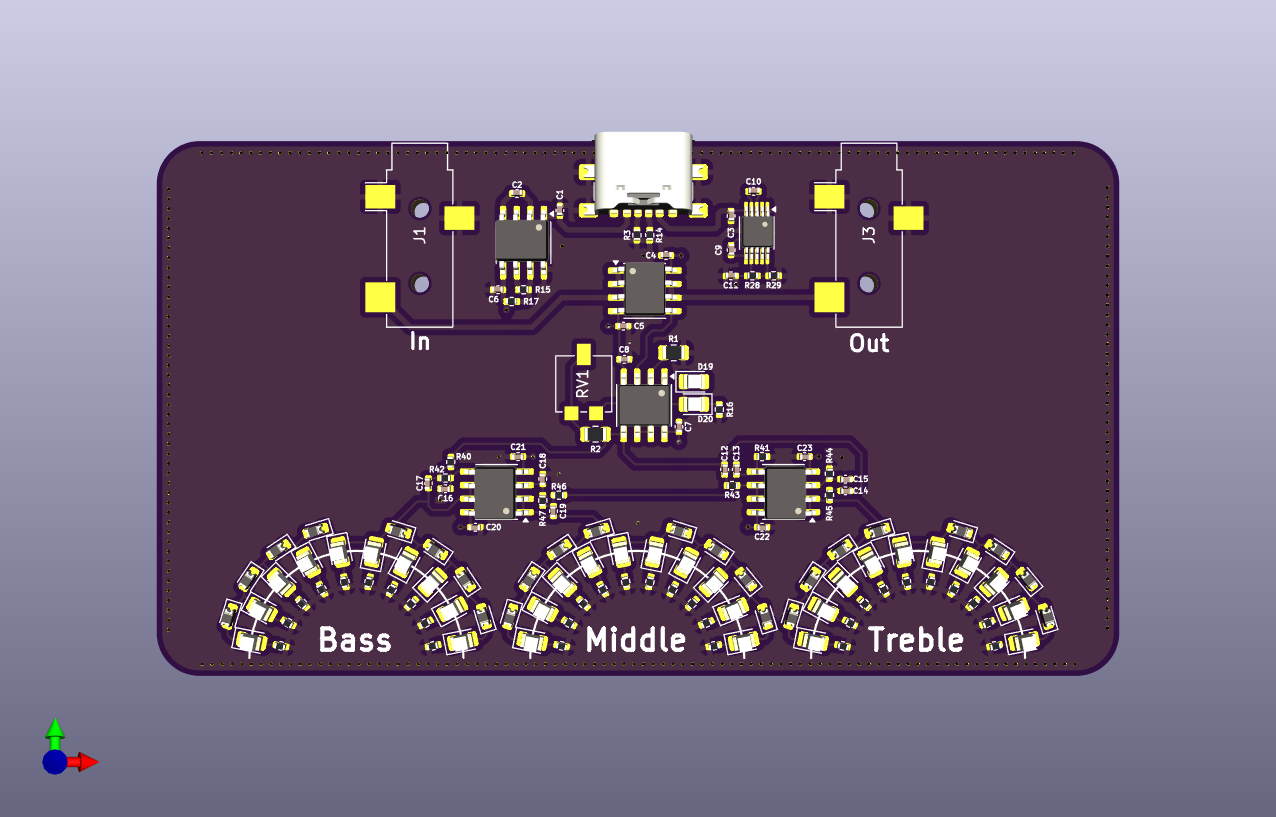
Laid out the USB C connector and the regulators toward the top center. This really makes the circuit look like Air Buster from FF7.
Discussions
Become a Hackaday.io Member
Create an account to leave a comment. Already have an account? Log In.