 Martynas
PCBs finally arrived.
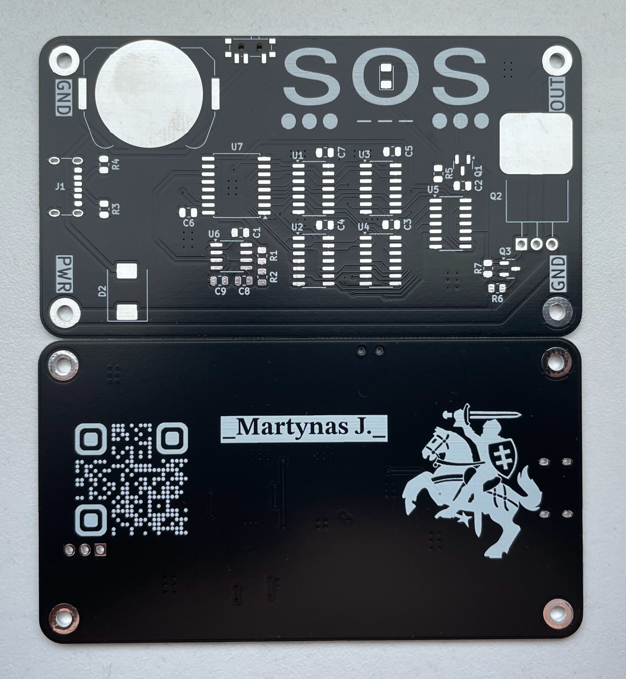
Noticed some issues while soldering:
- Coin battery holder should be flipped. It is difficult to insert battery if USB-C socket and CC line resistors are soldered.
- Turns out I don't have any 330nF 0805 capacitors at hand for C9 and no 1M ohm resistors for R2. It is needed for setting 555 timer frequency to 2Hz. I soldered two 100nF in parallel for C9 and 620K ohm resistor for R2 instead. This should give 5.8Hz frequency.
- I don't really know why I chose 2.5mm holes for corner connections. I think 3mm holes would be better.
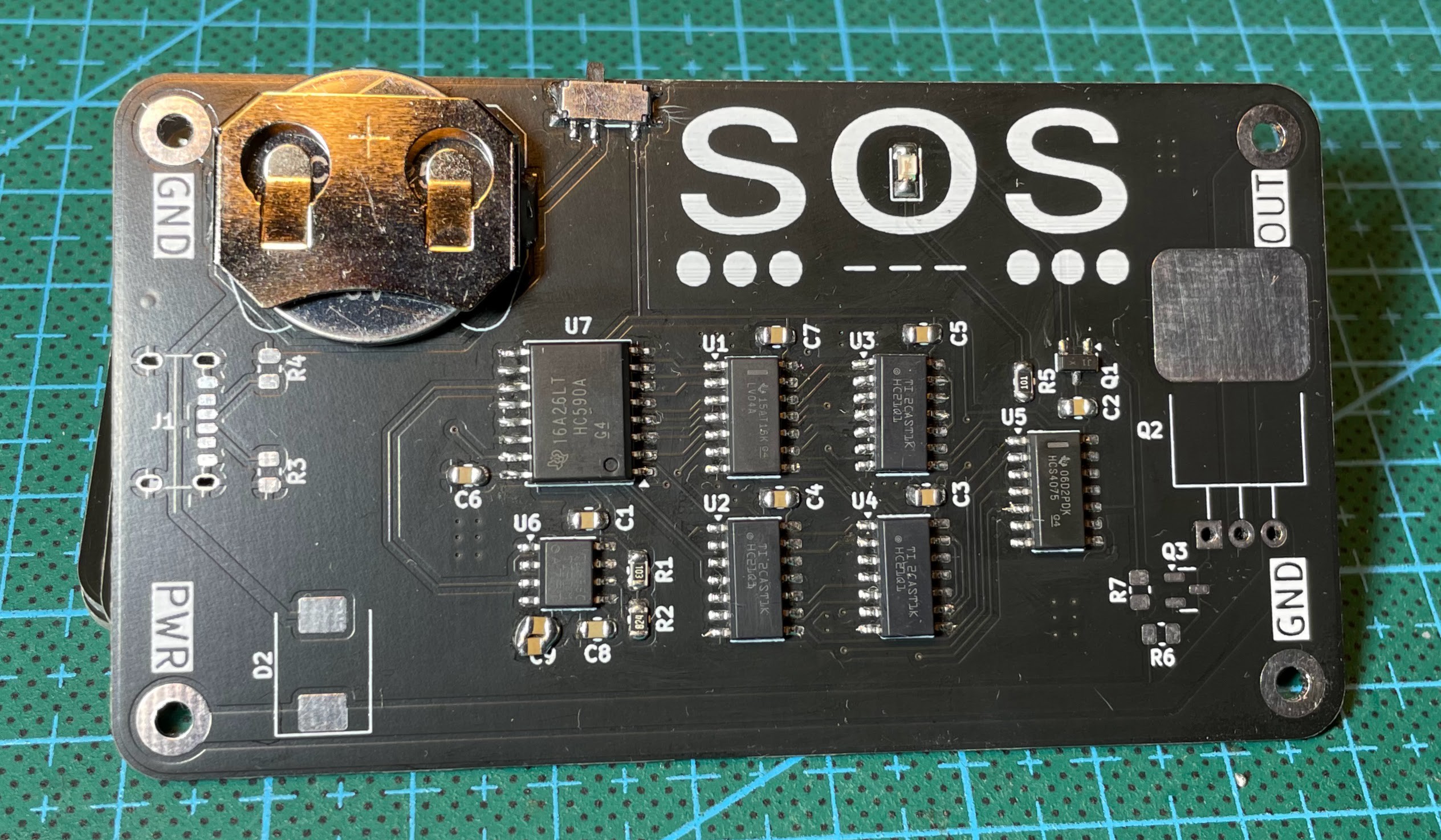
I have soldered two PCBs. One powered by coin battery and driving small green LED.
Another powered from USB-C and driving brighter white LED with possibility to connect external load.
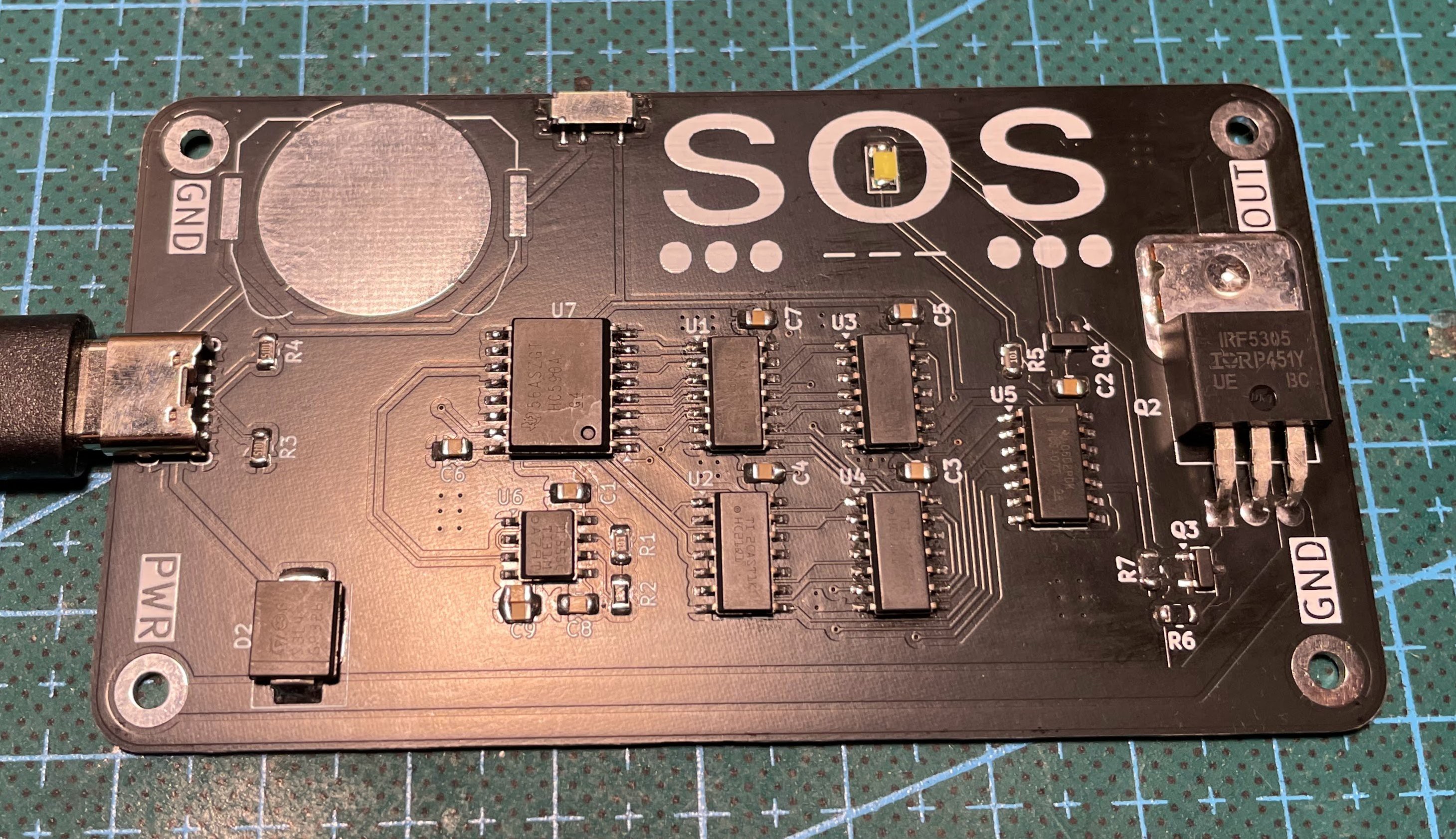
Board thickness is 5.7mm (PCB 1.2mm + TO-220 4.5mm).
Discussions
Become a Hackaday.io Member
Create an account to leave a comment. Already have an account? Log In.