 cheetah_henry
ATtiny 2-series
ATtiny3227 as part of the ATtiny 2-series (sometime is also referred as tinyAVR 2-series) is released in the middle of global Covid-19 pandemic, the ATtiny 0 and 1-series were released a couple of years earlier. Don't be fool by the name of ATtiny, it is not the classic ATtiny products such as ATtiny 31 or ATtiny 85, it is actually more powerful than many classic ATmega products such as the ATmega328P used in the Arduino Uno/Nano. Ever since its launch, I likely it very much and had ever since phase-out all my Arduino Uno/Nano/Pro Micro since 2017 with ATtiny 1 and 2-series for all my 8-bit MCU projects.
When using the board as an ATtiny3227 Development Board, it comes with the following peripherals and features
- 32kB Program Memory (Flash)
- 3kB RAM - 256 bytes data EEPROM
- Capable of operating at 1.8 - 5.5v
- Running at up to 20 MHz with internal clock
- 6 channels Event System
- Configurable Custom Logic (CCL)
- Single pin UPDI programming interface
- 12-bit Differential ADC with Programmable Gain Amplifier / 15-channel ADC (Single-ended)
- 1 x Analog Comparator with internal DAC reference
- 1 x 16-bit Timer/Counter type A (TCA)
- 2 x 16-bit Timer/Counter type B (TCB)
- 1 x 16-bit Real Time Counter (RTC) with Periodic Interrupt Controller (PIT)
- 2 x USART
- 1 x SPI
- 1 x I2C
Software development can be done with Microchip's MPLAB X IDE or Microchip Studio (Windows-only). It can be used as an Arduino by installing megaTinyCore to the Arduino IDE. Personally, I setup my own development environment with avrdude, VS Code and avr-gcc that I described in my blog.
The ATtiny3227 requires a UPDI programmer for uploading code to the device. A SerialUPDI can be created using a USB-Serial Adaptor.
Specifically to this Business Card board, when using it as an ATtiny3227 board, the Slider Switch SW3 allows to select the power source either from the 3V 2016 coin cell battery or from external power source via the Vin pin on the break-out connector. This allows user to connect a 1.8v, 3.3v or 5v power source and program the chip to run up to 20MHz through the setup of the fuse and the configuration of the prescaler in the CLKCTRL register.
Bare metal programming
So far what I shown in my software implementation are based on bare metal (i.e. directly access the registers in ATtiny3227) programming, the new ATtinys are easy to program, and I high recommend to read the Tech Brief AVR1000b: Getting Started Writing C code for AVR first. The section 3.1 of the ATtiny3227 Datasheet is a table called "I/O Multiplexing" which is kind of the pinmap of the MCU and probably the most-often-refer-to page for bare metal programming.
Here is a blinky program when using the board as a ATtiny3227 development board, there is not much different from any blinky program, except that the SW3 should be switch to Vin and connect a 5v power source through the Vin pin on the break-out connector so that the board can be programmed to run at 20MHz. Remember to change the `F_CPU` value in Makefile as well as in .vscode/c_cpp_properties.json to `F_CPU=20000000UL` prior compiling the code if you choose to follow my development environment setup.
As our board has 12 LEDs, any one of the LEDs can be used as the blinky LED, except that all the LEDs is part of the charlieplexing configuration, so it need to keep the unrelated charlieplexing pins "float" and only configure the two pins corresponding to the LED that you'd like to blink. The code shows the use of LED D12 as the blinky LED.
#include <avr/io.h>
#include <avr/interrupt.h>
#include <util/delay.h>
#include <stdio.h>
#include <stdlib.h>

#define BAUD_RATE 115200UL

static int USART0_sendChar(char c, FILE *steam) {
    while (!(USART0.STATUS & USART_DREIF_bm)); // Wait if Data Register Empty Interrupt Flag is not set
    USART0.TXDATAL = c;
    return 0;

}

static FILE USART_stream = FDEV_SETUP_STREAM(USART0_sendChar, NULL, _FDEV_SETUP_WRITE);

static void USART0_init(uint32_t baud_rate) {

    PORTA.DIRSET = PIN1_bm;                        // PA1 as TxD
    PORTMUX.USARTROUTEA |= PORTMUX_USART0_ALT1_gc; // map PA1 as alternative pin for TXD

    USART0.CTRLC = USART_CMODE_ASYNCHRONOUS_gc | USART_PMODE_DISABLED_gc | USART_SBMODE_1BIT_gc | USART_CHSIZE_8BIT_gc;
    USART0.BAUD = (uint16_t) (F_CPU * 64 / (16 * (float) baud_rate) + 0.5);
    USART0.CTRLB |= USART_TXEN_bm;

    stdout = &USART_stream;

}

void configLED12() {

  PORTB.DIRCLR = PIN5_bm | PIN6_bm;  // reset PB5 and PB6 to INPUT
  PORTB.DIRSET = PIN4_bm | PIN7_bm;  // set PB4 and PB7 as OUTPUT for controling LED D12
  PORTB.OUTCLR = PIN4_bm | PIN7_bm;  // reset both pins's state to LOW

}

int main(void) {

    char str[] = "Hello World";

    // clear Prescaler to run at 20MHz
    _PROTECTED_WRITE(CLKCTRL.MCLKCTRLB, !CLKCTRL_PEN_bm);

    USART0_init(BAUD_RATE);

    configLED12();

    while (1)
    {
        printf("%s\n", str);
        PORTB.OUTTGL = PIN7_bm;  // toggle LED D12 (PB7 HIGH/LOW, while PB4 remains LOW)
        _delay_ms(1000);
    }

    return 0;
}
The silkscreen on our board shows that the USART port is at PA1 (TXD) and PA2(RXD), a closer look at the I/O Multiplexing table indicated that the pins are the alternative pins for USART0 and the default pins for USART1. You can either use the USART0 (with alternative pins) or USART1. The code we used configures the USART0 and set the altenative pin position through PORTMUX configuration. For routing USART output to stdout, you can further read at Microchip Tech Brief TB3216 Getting Started with USART for more details.
Arduino with megaTinyCore
From time to time I still use Arduino IDE, mainly because I don't want to re-invent the wheel of writting some of the sensor/device driver libraries. The installation of megaTinyCore is available on megaTinyCore Github page.
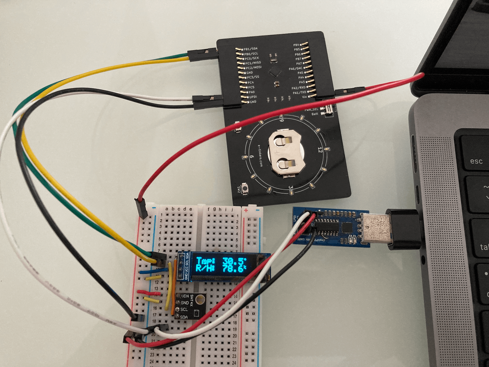
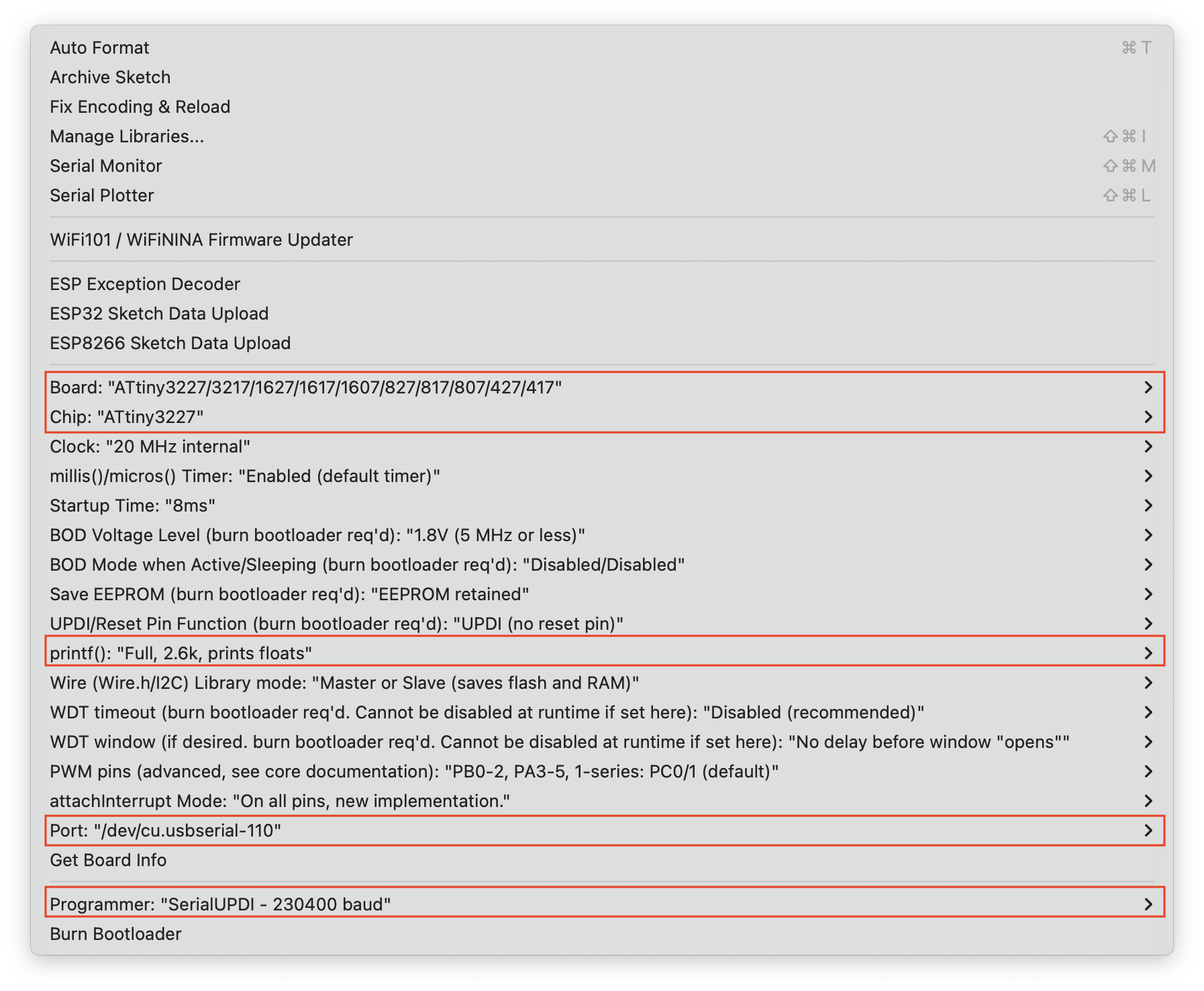
The sketch below read the data from an SHT41 temperature/humidity sensor and display the data on a SSD1306-based OLED display at every 30 seconds. The code is very straightforward just like any Arduino code. Since I'm using the sprintf() function for formatting the floating point value, so other than configuring the usual settings on the Tools -> Boards from the Arduino IDE drop down, the printf() option need to be turned on as shown below.
#include <Wire.h>
#include <SHTSensor.h> // provided by Sensirion. https://github.com/Sensirion/arduino-sht
#include <SSD1306Ascii.h>
#include <SSD1306AsciiWire.h>

#define OLED_ADDRESS 0x3c

SHTSensor sht(SHTSensor::SHT4X);
SSD1306AsciiWire oled;

/* A helper function to print the degree symbol on LCD display */
void printDegreeSymbol() {
  const char degree[6] = {0x00, 0x06, 0x09, 0x09, 0x06, 0x00};
  Wire.beginTransmission(OLED_ADDRESS);
  Wire.write(0x40);
  for (uint8_t i=0; i<6; i++) {
    Wire.write(degree[i]);
  }
  Wire.endTransmission();
}

void setup() {
  Wire.begin();
  Wire.setClock(400000L);
  delay(10);
  oled.begin(&Adafruit128x32, OLED_ADDRESS);
  oled.clear();
  oled.setFont(lcd5x7);
  oled.set2X();

  if (!sht.init()) {
    oled.print("SHT Failed");
    while(1);
  }

  oled.setCursor(0, 0); oled.print("Tmp:");
  oled.setCursor(0, 2); oled.print("R/H:");
  oled.set1X();
  oled.setCursor(108, 0); printDegreeSymbol();
  oled.setCursor(108, 2); oled.print("%");
  oled.set2X();

}

void loop() {

  double t{0.0};
  double h{0.0};

  if (sht.readSample()) {
    t = sht.getTemperature();
    h = sht.getHumidity();
  }

  char msg[20] = {0};
  sprintf(msg, "%2.1f", t); oled.setCursor(60, 0); oled.print(msg);
  sprintf(msg, "%2.1f", h); oled.setCursor(60, 2); oled.print(msg);

  delay(30000);

}
Discussions
Become a Hackaday.io Member
Create an account to leave a comment. Already have an account? Log In.