Circuit Diagram of Speed Control of DC Motor Using MOSFET
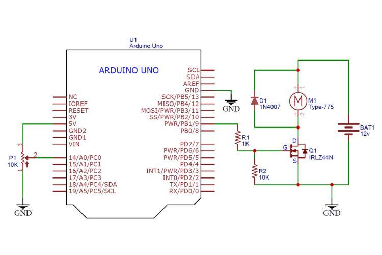
Here's the simple circuit diagram for controlling a DC motor's speed using an Arduino and a MOSFET. This minimal-component design is straightforward to understand. For direction control, refer to our L293D project.
Circuit Diagram Overview:
Components: Arduino UNO, MOSFET, 1k Ohm resistor, 10k Ohm potentiometer, diode, 12V power supply.
Connections:
- MOSFET connects the Arduino to the motor, serving as a driver.
- The 9th pin of the Arduino (PWM capable) regulates the MOSFET.
- The potentiometer connects to 5V, ground, and A0 for adjustable voltage input.
- A diode safeguards against reverse EMF from the motor.
Let's proceed to the components assembly.
Component Assembly of Speed Control of DC Motor Using MOSFET
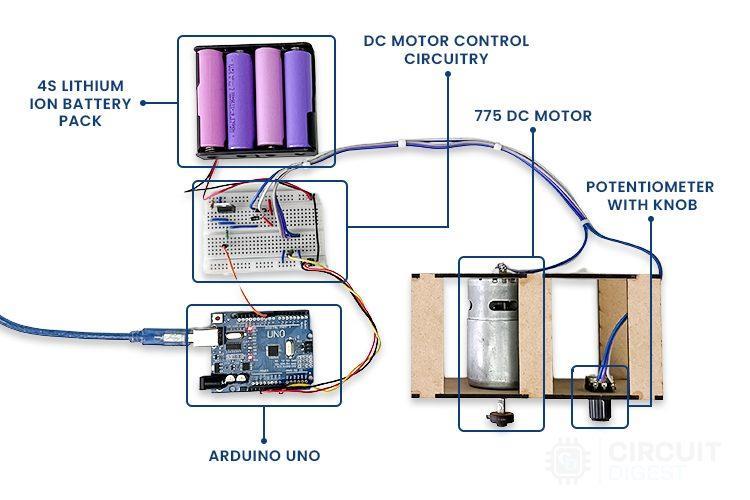
We used a breadboard to assemble the circuit, a power bank for the Arduino UNO, and a 4S Li-ion battery pack for the motor. The connections follow the previously discussed diagram.
Ensure the breadboard is in good condition to avoid connection issues.
Now, let's dive into the code explanation.
Let's Code the Arduino
The code declares the 9th pin as `motorPin` and sets it as an OUTPUT in `setup()`.
In the `loop()`, it reads the potentiometer value and uses `map()` to scale the 10-bit ADC value (0-1023) to the 8-bit PWM range (0-255) for `analogWrite()`, ensuring accurate motor speed control.
Next, let's move to the simulation part of the project.
For the code, visit the Git Repo: Arduino DC Motor Speed Control Using MOSFET.
Conclusion
As expected, the project worked successfully, confirming the design's effectiveness. For more detailed information about this project, visit the official article on Arduino DC Motor Speed Control using a MOSFET transistor. The article covers various topics, including how to choose the right MOSFET for your project, step-by-step simulations, and additional tips for optimizing performance. This comprehensive guide will help you understand the intricacies of motor control and ensure your project's success.
 peterbdavenport
 cele9999