Context:
I present to you today my end-of-semester project, completed as part of my engineering school curriculum. The project specifications focused on interactive art, allowing me to choose between creating an original object or recreating an iconic object from a film. I decided to create an entirely new object. My goal was to design a magnetic levitation lamp in the shape of a cloud, which I would have turned on with a push button. There would have been LEDs in the base and in the cloud. However, things did not go as planned...
1. First idea: the magnetic levitation lamp.
This technology has fascinated me since I was a child, and I have always wanted to understand and build a levitation module by myself.
1.1 First attempt:
I bought a DIY KIT of a levitation module on Aliexpress for €25. After two weeks of waiting, I received it and spent my weekend soldering it. Once plugged in, nothing worked, not even the LEDs. After checking all the components, still nothing. After asking one of my professors to check my circuit, we still found nothing. It was probably a scam, but it cost me a week of time.
1.2 Second attempt:
After a lot of research on the internet, I came across this video:
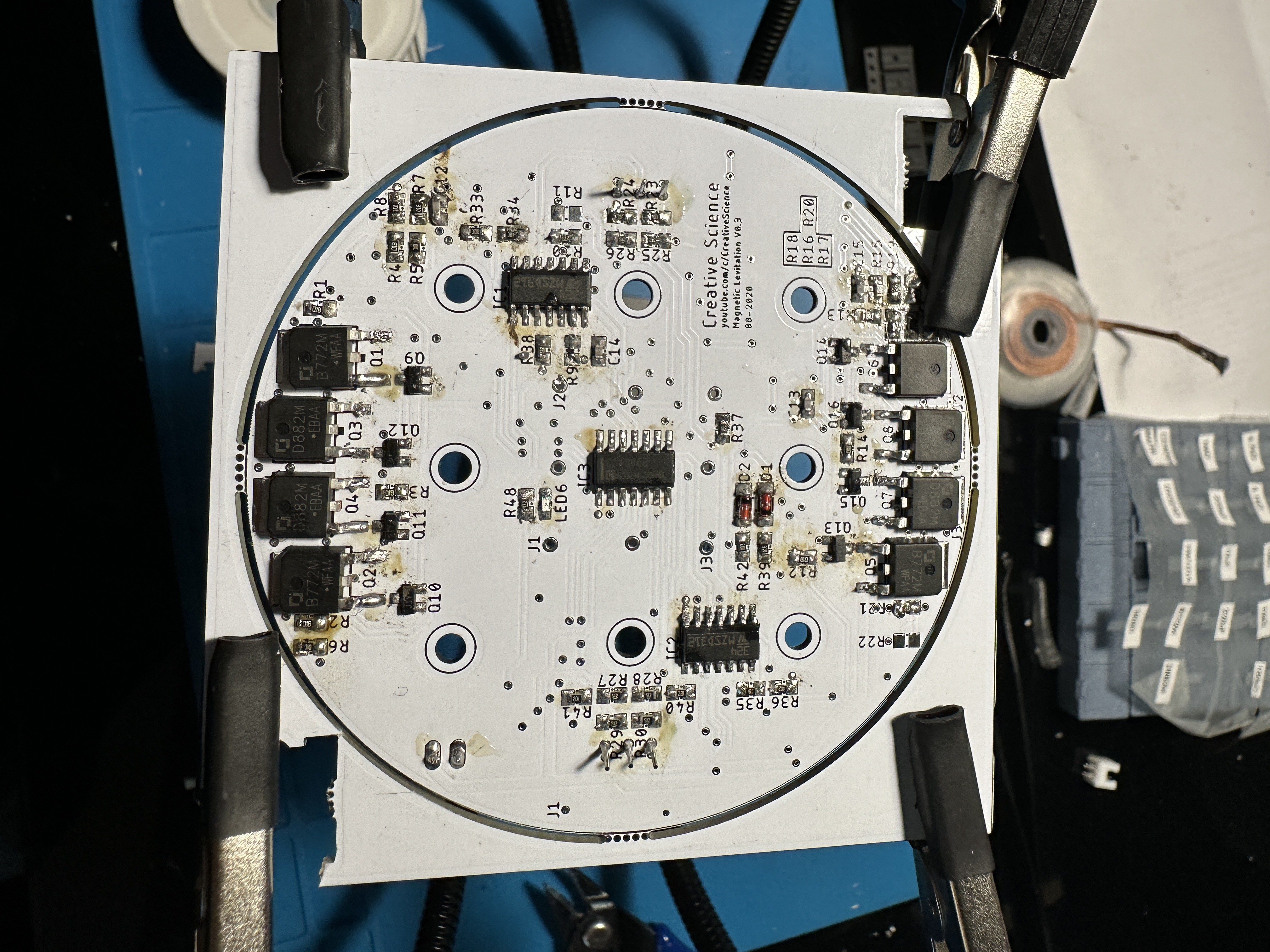
The channel is professional, and it's not a dream seller because he has nothing to sell. He left a GERBER file link providing access to the PCB diagram. Not even knowing what it was at that time, I thought my problem was solved. But no, it was just the beginning of a very long adventure. From this GERBER file, I spent more than two weeks reverse engineering the electronic schematic. It was the first time I used software for electronics. In my case, I used EASYEDA. After these two weeks of design, I spent another week designing the PCB schematic, another discovery.
These steps took a lot of time because, being new to the field, I had to watch a lot of tutorials on YouTube and document myself on forums. Once the entire design was finished, I was able to order my parts via JLCPCB and LCSC. Initially, I planned to order my already assembled
electronic board, but due to the price, I had to take the electronic board and the components separately.
Ten days later, I received everything except the PCB stencil that I had taken to greatly facilitate the assembly. The delivery man gave me one out of the two packages (spoiler alert: it arrived a few days before the end of my project)...
Note to self: never remove SMD electronic components from their packaging at the risk of dropping them on the floor and spending an afternoon picking them up and sorting them...
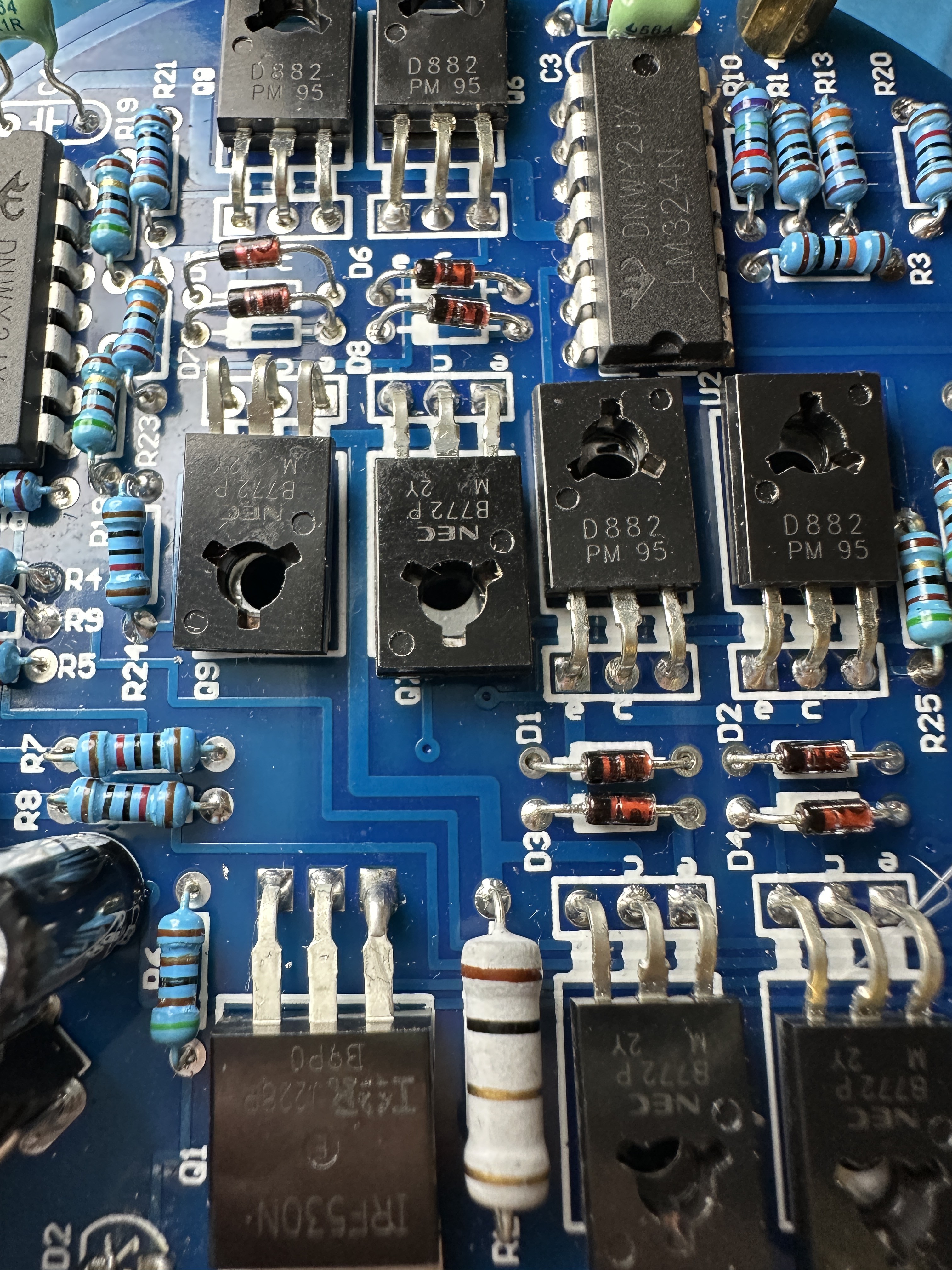
During a week (my vacation week), I then learned to assemble SMD components on my PCB. It was very difficult given that I had a low-end soldering station. After burning all my soldering iron tips, I finally finished assembling my electronic board. Once plugged in, some components burned out because my soldering was not precise and there were shorts.
1.3 Last attempt:
After this failure that took me several weeks, I decided it wasn't over. I decided to make an investment that would always serve me: I bought a good soldering station. Then I assembled another electronic board. The soldering being of much higher quality, the board had no short circuits. However, once plugged in, nothing burned out, but nothing worked either, except for a few LEDs. At that point, losing motivation and running out of time, I decided to move on to plan B.

2. Second idea: the lamp with a screen and the game of life..
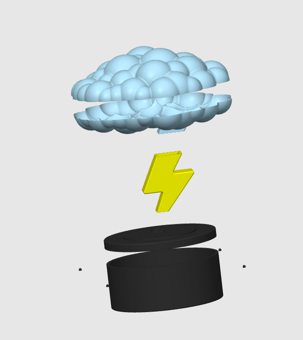
The goal of this plan B is simple and more easily achievable: to make a lamp in the shape of a cloud with a lightning bolt connecting the base and the cloud, all with a color game at the level of the LEDs. This lamp was to have a button to turn it on and a screen displaying the game of life in the background. The game of life is a cellular automaton invented by John Conway where cells on a grid evolve according to simple rules of birth, survival, and death, creating complex and dynamic
patterns from simple initial configurations. This was displayed on the ESP32 screen. I found a ready-made code, then I added an interactive side with push buttons and incorporated the LEDs. There were two weeks left before the end of the project, and I was rather confident. However, I made a terrible mistake by bringing it to university because the screen of my ESP32 broke in my bag. The school no longer had this model in stock. So I had to move on to plan C, and that's when the stress started to build!
3. Last idea: the bedside lamp with an integrated alarm.
There was only a week and a half left before the deadline, and after all I had done for this project, I couldn't present myself on the day without anything. That's why I started by making my 3D modeling, using the same base as idea number 2. I master Fusion 360, so I made my base and my lightning bolt on it. However, for the cloud, I made it on Blender, another software I discovered through this project. After a few prototypes, I managed to get what I liked. Then I found a small speaker at home, so I went for a bedside lamp project serving as an alarm. The code works as follows:
Set the alarm time:
#define alarmHour 15
#define alarmMinute 29
Set the current date:
setTime(15, 28, 55, 1, 1, 2024);
When the time matches, the lamp lights up in red (the least brutal light, I find) and a continuous sound is generated. To turn it off, simply press a button, and the alarm will sound again in 24 hours. To turn it on as a bedside lamp, just press another button.
Conclusion:
In conclusion, I greatly enjoyed working on this project. I discovered a new field: electronics. I learned how to create an electronic schematic and a PCB, as well as how to solder SMD components. I also learned how to use the ESP32. Thanks to this project and all these discoveries, I now know which field I want to specialize in: electronics.