Once the PCB’s arrived and were assembled, I set out to test the individual components on the AVR Data Recorder. Once again, AttoBASIC was indispensable for this purpose. As of this post, the newest version of AttoBASIC (V2.34) is now available and adds support for several more AVR’s, including the ATtiny84 and ATtiny85.
Testing was easy and all the functional blocks worked as expected. I had to build a separate precision 1.000 volt reference to calibrate the analog front end but that was a fairly easy project.
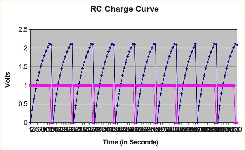
One of the tests I ran was using the digital output to short a large capacitor then using the analog comparator with the Vref set to 66% of the charge voltage, wait for the charging voltage to reach the analog comparator’s trigger threshold. The data was stored in the “data file” (off-chip EEPROM), later retrieved and imported into a spreadsheet so the data could be graphed.
The program used is shown below:
5 EMI $0C #CLEAR SCREEN
10 DFI 0 8; DFF 2; DFX # INIT 8 PAGES, 2 FIELDS PER RECORD, RESET ADRESS POINTER
15 DIG 1; ADG 0 2      # INSURE CAP IS SHORTED AND SET CH 0 GAIN TO 1X
20 R:= 16              # 2V ACO REF (0.1X ON ACO)
25 ACR R; SLP 5        # SET ACO REF AND DELAY 500MS
30 PRINT "TESTING ACO TRIGGER LEVEL...~"
35 FOR N= 1 10         # LOOP TEST 10 TIMES
40 PRINT "RUNNING TEST   # "; PRINT N; PRINT "~" # PRINT TEST #
45 DFL ADC 0; DFL ACO
50 DIG 0               # RELEASE CLAMP ON CAPACITOR
55 SLP 5; DFL ADC 0; DFL ACO   # SLEEP 500MS, TAKE AND STORE READING
60 PRINT "SAMPLING ...~"
65 IF ACO = 0 THE
70 GOTO 55                   # KEEP TAKING READINGS TILL ACO TRIGGERED
75 PRI "~ACO TRIGGERED AT "; PRI ADC 0        # PRINT THE VALUE
80 DIG 1                                      # CLAMP THE CAPACITOR
85 NEXT
The image below is the resulting data is presented as a charge voltage vs. time graph. The magenta line shows the state of the digital output, which was used to discharge the capacitor. The blue line shows the charge and discharge voltage across the capacitor.
 Analog Comparator Test
The following program shows a typical usage for recording the 32-bit RTC value and all four channels of the ADC; Analog Channel 0, Analog Channel 1, TRMS Channel and the current reading channel. The RTC value is used as a “time-stamp”. Once the data is captured, it can be dumped from the AVR Data Recorder’s “data file” and imported into a spreadsheet for analysis.
5 DFI 0 1 ; DFX # init the 1st page as we need only 80 bytes and reset pointer
10 RTI 2; RTR   # set to 100mS update interval and reset RTC count
15 FOR N=1 10   # contain to 10 iterations
20 PRINT "N= "; PRINT N; RTP            # optional - print RTC on console
25 A:=PEEK $5 $65; B:=PEEK $5 $64   # RTC registers at 0x0562 {MSB} to 0x0565 {LSB}
30 C:=PEEK $5 $63; D:=PEEK $5 $62   # "$" means hexadecimal value follows
35 DFL D; DFL C; DFL B; DFL A       # log all 32 bits to data file MSB to LSB
40 DFL ADC 0; DFL ADC 1             # log Ch 0, 1 to data file
45 DFL ADC 2; DFL ADC 3      # log TRMS and Current sense to data file
50 FOR T=1 30                # SET UP 30 SECOND WAIT PERIOD
55 SLP 6                     # SLEEP FOR 1 SECOND
60 NEXT T                    # CONTINUE LOOPING
65 NEXT                           # loop to sample and record
70 DFF 8                    # set data format to 8 fields per record
75 # once finished, use "DFD 0 1" to capture the data
I later went on to monitor the dwelling’s water heater usage. It was a modified form of the above program. I had to design a Rogowski Coil and a front-end circuit to measure the water heater’s A/C current. I documented the construction technique in a PDF file here.
The image below shows the water heater “on” time over a 7 day period. Though, the actual time is difficult to see in the graph.

I spent a considerable amount of time creating a user manual and application note for this project. It contains information on the use of the AVR Data Recorder, specifications and programming techniques. The PDF file is here.
 Scott
Scott
Discussions
Become a Hackaday.io Member
Create an account to leave a comment. Already have an account? Log In.