Act I - The gift
Where I live, often boxes with 'Zu verschenken' (To give away) are placed on the street and at one point, my girlfriend found a typical wooden clock with LED's behind the front over there.
It was working, but she didn't want it in the end and I was interested to place it at my nightstand (so as not to need my phone to know the time at night, but also to distract myself in the morning before getting up).
When it would be running from batteries, the clock had a function to disable the display at night. You could wake it by tapping on the housing, which would trigger an internal piezo contact microphone. Sometimes this even worked.
The original power supply was also available, so I didn't want any batteries, unfortunately, the disable-at-night-function didn't work when powered by the supply. Taking it apart, rewiring the power supply from the supply input to the battery input on the PCB worked, but when trying it out at night, it would have reset itself in the morning and had to reconnect to a time server, so all in all: not great.
In the end, it ended in the parts bin.
Act II - The mornings
My girlfriend is not great at getting up in the morning. To put it mildly. She would therefore set up to 10 alarms, with a 5-10 minute interval, up to an hour before she really needed to get up. Furthermore, she has to get up a bit earlier than I do, but it would also wake me up, let me fall asleep again, wake me up again, and so on. I was not a fan.
Apart from that, she always wanted a radio alarm clock, with the one from Groundhog Day explicitly mentioned several times. But it should also play Deep Oldies, a radio station not playing any ads, but with her kind of music. 'Unfortunately', that meant standard FM alarm clocks were no option. Now, there also are internet radio alarm clocks these days, but I haven't found Deep Oldies in the usual radio stations yet or on for example Streamurl, so my hopes of one of those being able to play Deep Oldies were slim. (On the other hand, I didn't search that well, because I might've ended up finding something, which would mean this project was not necessary...)
Act III - The research
Now, I knew a flip type clock as in the movie was not really feasible at this point. I could have probably managed it, but not given my available time and the additional research/sourcing I had to do for that. But I did still have the 'wooden' clock. So I took that apart again (did I already mention that they spent a lot of glue to close it up?) and started measuring on the cable between the display PCB and the main PCB.
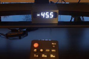
It featured a 13 pin, 2mm pitch band cable, nicely numbered on both side. As I hoped, it was just a 4 number, 7 seven segment display with a common anode (that's a common VCC, I always seem to forget the naming convention of anode/cathode), but with 2 dp connections as in the table below. See one of the images for the display when everything is turned on.
| Pin | Connection | Original PCB connection |
|---|---|---|
| 1 | CA 3 | Output (3V3) |
| 2 | segment c | 27Ω to sink (GND) |
| 3 | CA 2 | Output (3V3) |
| 4 | segment e | 27Ω to sink (GND) |
| 5 | CA1 | Output (3V3) |
| 6 | segment g | 27Ω to sink (GND) |
| 7 | segment f | 27Ω to sink (GND) |
| 8 | segment dp1 - CA1: alarm - CA2: point 2 - CA3: double point (bottom) - CA4: point 4 | 100Ω to sink (GND) |
| 9 | segment a | 27Ω to sink (GND) |
| 10 | segment b | 27Ω to sink (GND) |
| 11 | segment d | 27Ω to sink (GND) |
| 12 | CA 4 | Output (3V3) |
| 13 | segment dp2 - CA1: double point (top) - CA2: Wifi symbol - CA3: not connected - CA4: not connected | 200Ω to sink (GND) |
Internally, the LED's were powered from 3V3, with the resistors on the cathode (GND) side to limit the current. I have to say I didn't quite understand logic behind the resistor values. It seemed to be a kind of R=200 [Ω] / (amount of segments in parallel) or R=400 [Ω] / (amount of dp segments in parallel), which didn't make sense to me, since they wouldn't be powered all at the same time anyway.
In the end, I just ignored the...
Read more » Quin
Quin
 Tim S
Tim S
 RodolpheH
 Enrico Gueli
 Saul Cozens