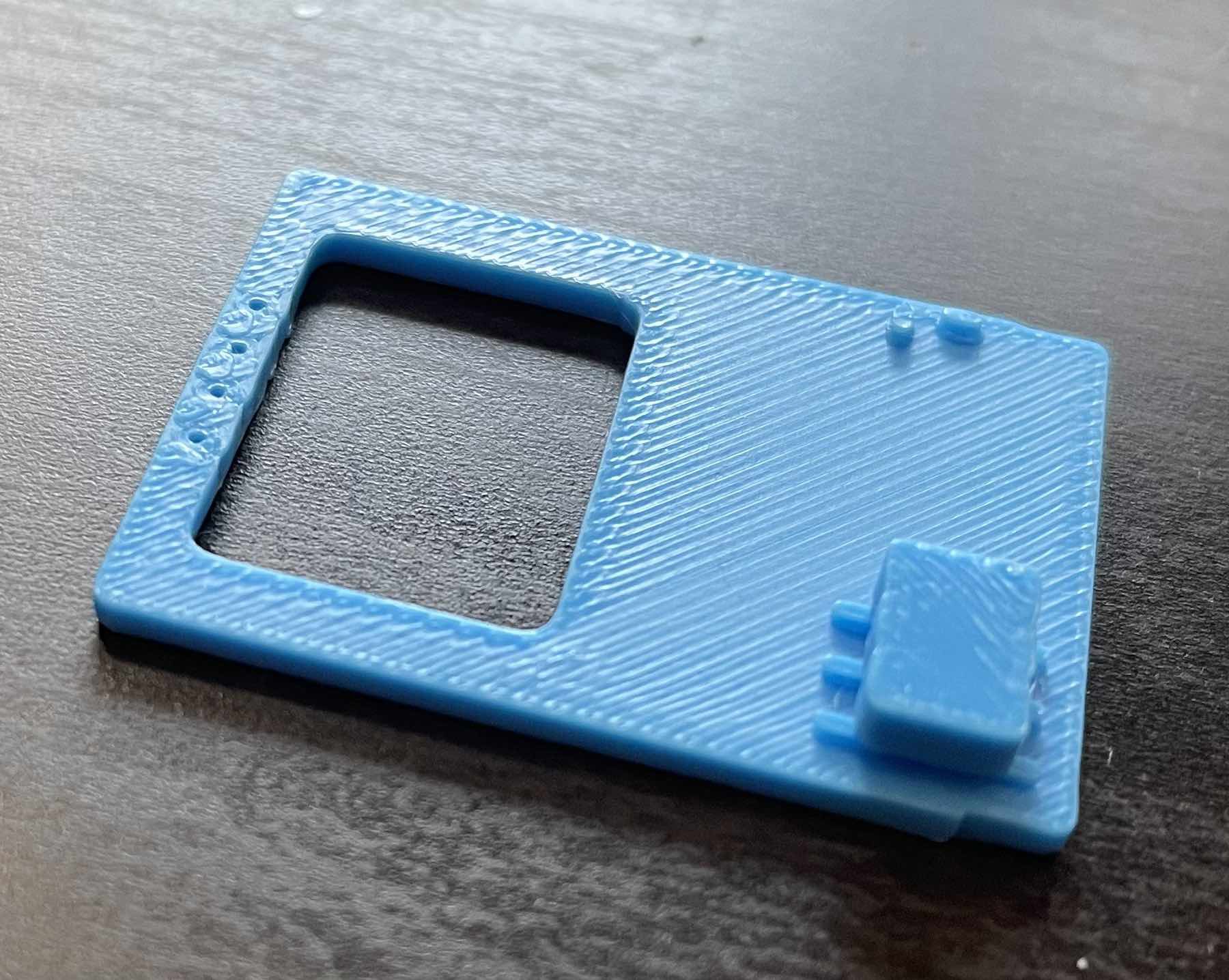
I've been working on the PCB recently and finally got a version working that I'm happy with (I think). Because I'm impatient, and want to avoid spending money where I can, I exported the generated STEP file from KiCAD and 3D Printed the board. I mostly did this so I could get a sense of size and check for component collision.

This printed version I clipped the header pins. It would be asking my printer for a lot to print those, and I didn't need to. I just wanted the bulk of it to get a sense of spacing. Also visible here are a couple of 0603 capacitors. One of the benefits of printing this is being able to actually look at the components. It's made me switch out the 0603s for larger 0805s. I'm not tight on space as I was when I was trying to make attach the display directly.
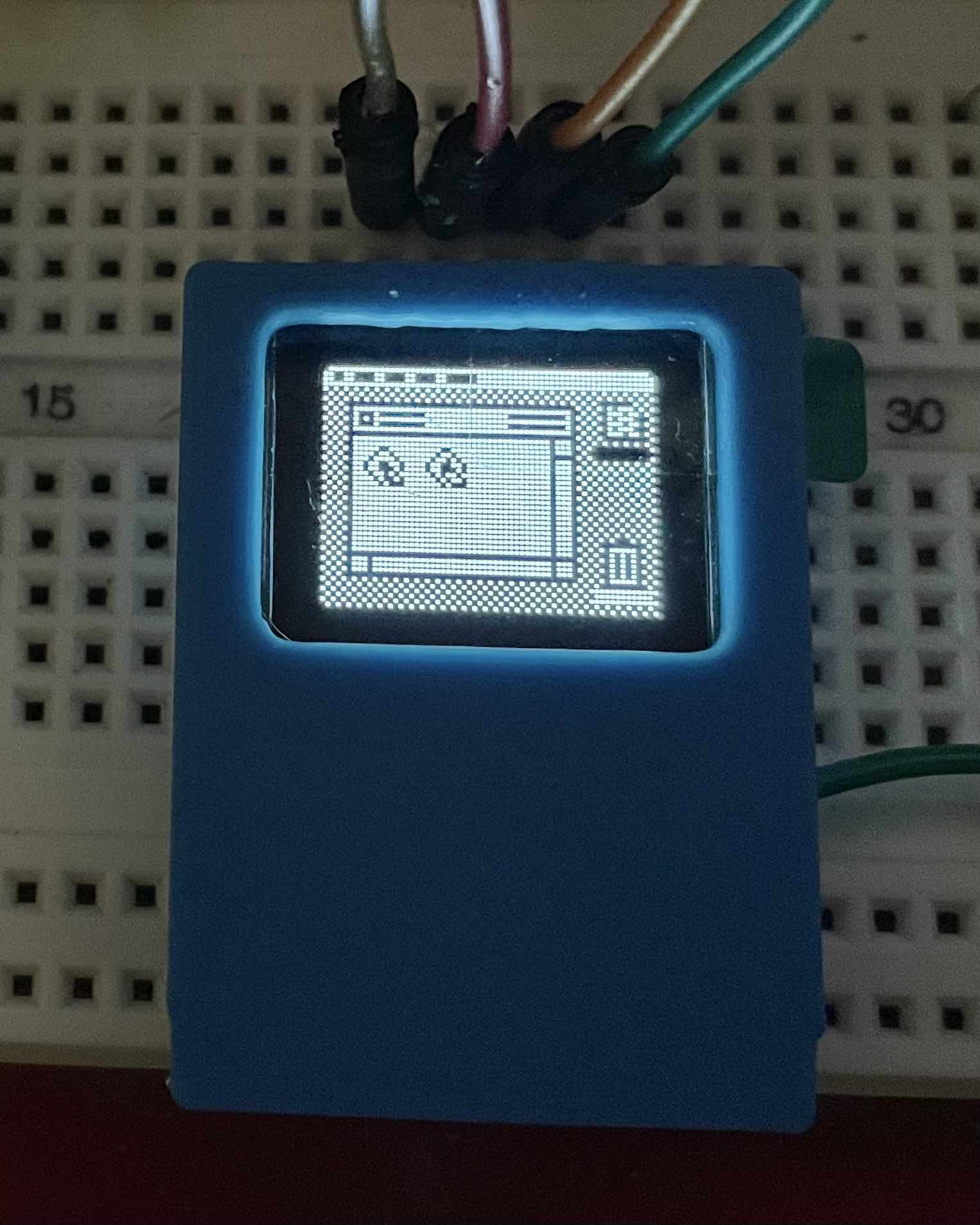
The main purpose is to see how the display fits:

Not bad! It's hard to see in this photo, but the display actually pops up a little at the top. I've decided to get the PCB manufacture, assemble and program one before I decide if it's worth trying to avoid. I have to remind myself to relax. This is just an SAO. I'm not building the Flux Capacitor, or the next iPhone. It's just a fun thing that (I hope) makes people smile a little.
 Aaron
Aaron
Discussions
Become a Hackaday.io Member
Create an account to leave a comment. Already have an account? Log In.