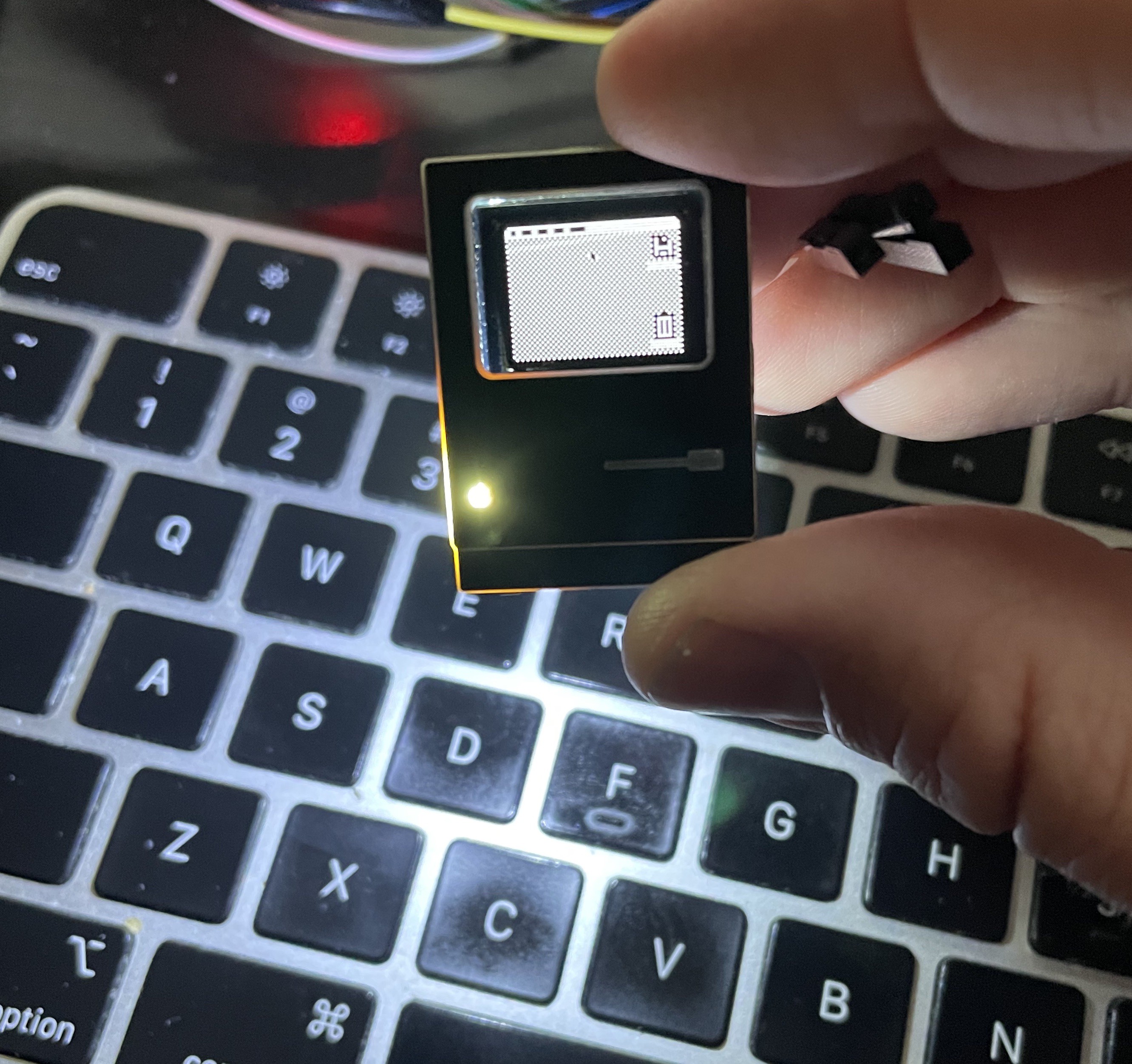
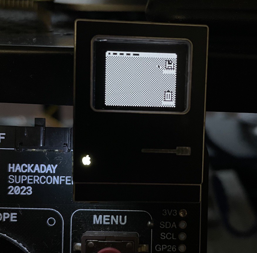
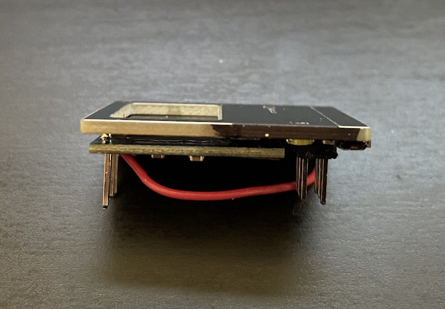
I got in the EEPROM and the LEDs for the apple logo, and hand soldered them in place. The pads are not intended for hand soldering - that said, I managed to make it work.

This is the LED at 3.3V with a 0 ohm resistor. It is shockingly bright. If someone needs a flashlight this will serve very well. Suffice to say that I need to figure out a more appropriate resistor. Through a happy accident, I found what I think is the right brightness level.

I plugged the board into my Vectorscope - which happened to have low batteries - and the LED brightness was just about right. I just have to measure the voltage, and do the reverse calculation to get the proper resistor value.
Even with the brightness toned down, it presents another problem. If you look up at that first picture, there's a lot of light bleed out the left side of the Mac. The LED is putting light through the PCB, and the translucent fiberglass center of the PCB acts as a light-pipe. The fix for that was simple, if a little hacky. I took a black sharpie and ran it over the edge where the light was bleeding.

When I get these boards made in white, I'm not sure the same solution will work as well. With the black soldermask, it's not really noticeable. With the white soldermask, even though its on the side, it'll kind of stick out. One wild (and expensive) solution would be to edge plate the board, so that there's a metal edge around the outside. It'd be pretty, but is only available in gold (ENIG) and I prefer the look of Lead-free HASL.
EEPROM Woes
I have run into another issue as I've been writing firmware. The EEPROM was not reliably writing or reading data. It would work 1 or 2 times out of 5. At first, I thought it might be too much resistance on the I2C lines. I removed the pull up resistors on the lines and of course realized that they're in parallel. If anything, they were lowering the resistance on the line. I thought it could be a timing issue - but no dice on that front either.
While thinking about how I2C works, it occurred to me that maybe my EEPROM calls were getting muddied by calls being sent to the display. I2C doesn't do anything to prevent the master from interrupting itself. And neither was I. Calls to the display are fired every loop, and the signals coming from outside the SAO can happen at any time. Since I2C data is relatively slow compared to the rest of the work the SAO was doing, it's a reasonable assumption I was tripping over my own shoelaces, so to speak.
I added an I2C 'reset' to the start of my EEPROM handler, and everything has smoothed out.
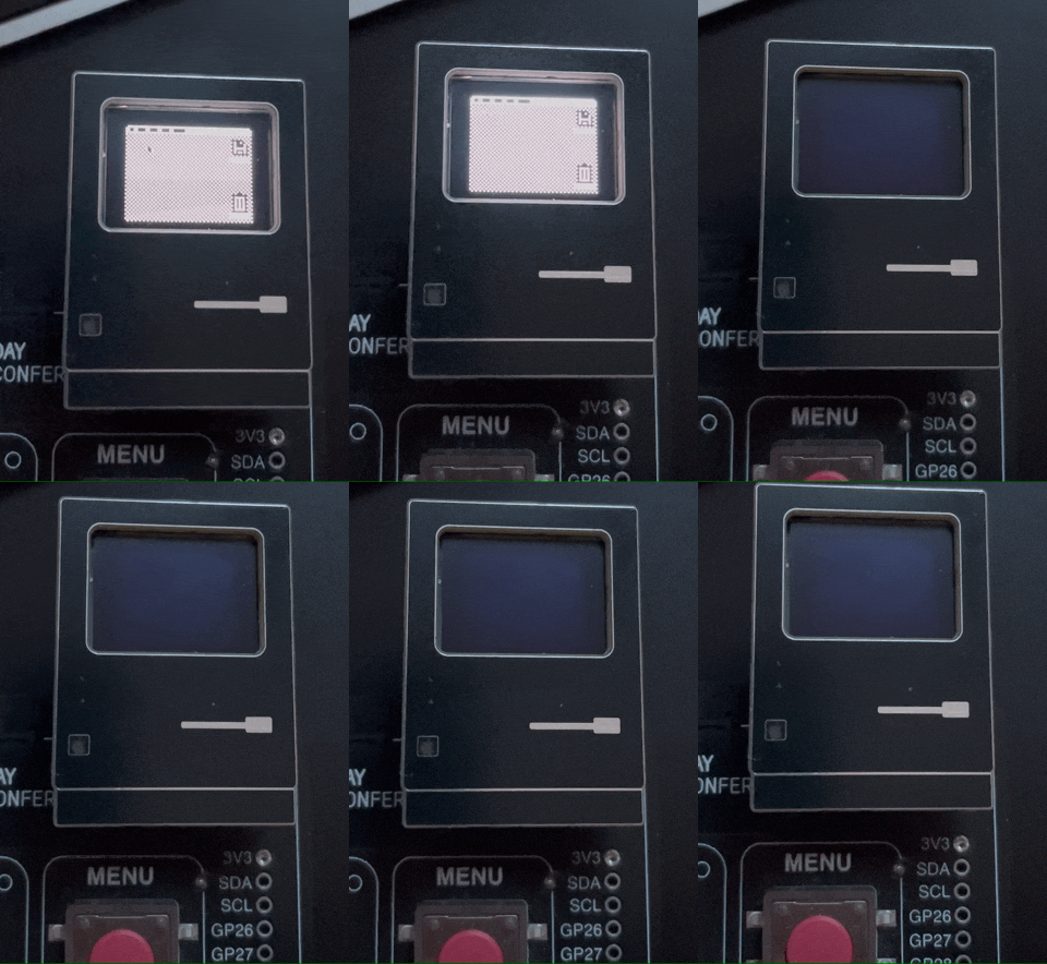
Finally, I found the point where my SAO stops working:

2.58V. It sure does try though.
 Aaron
Aaron
Discussions
Become a Hackaday.io Member
Create an account to leave a comment. Already have an account? Log In.