 eric
eric
I got the board working;
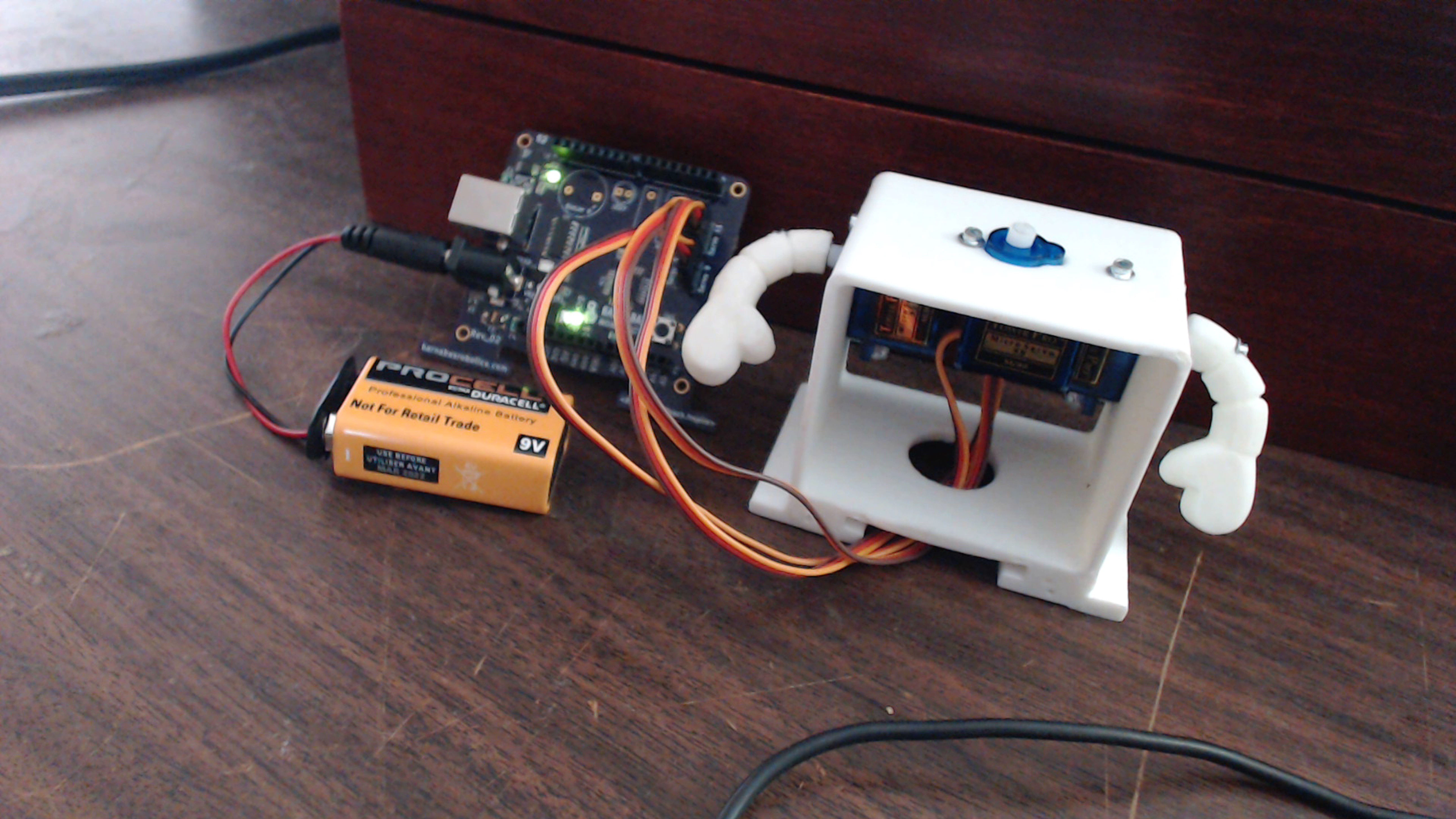
For the most part at least. The board gets power, can communicate via usb, accept code, and power components such as motors. However there is still a problem. That being the board's inability to receive power from USB. I think that the reason for that is a fundamental misunderstanding of p-mosfets.
I am well aware that p-fets act as inverters, only turning the channel on if the gate is low. However when routing the board I forgot that current only flows from source to drain in a p-fet. Thus the power management subsystem that allows the board to receive power via USB is essentially backwards.
So I need to Mcgyver the board in a way that allows me to verify this. You will probably be hearing from me again soon.
Till next time,
-Eric
Discussions
Become a Hackaday.io Member
Create an account to leave a comment. Already have an account? Log In.