 Marius Taciuc
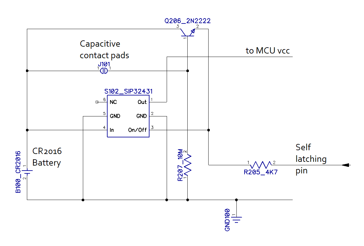
The circuit uses an amplifier BJT transistor for the contact pads. When these pads (J101) are being touched, there is a leakage current of a few microamps flowing through the resistance of the skin of the finger towards the base of the Q206. This small current is enough to make the BJT conduct enough to turn on the S102 static switch. When the SIP32431 switch turns on, it provides full power to the MCU, display and all the other circuits on the PCB. Once the MCU is being powered, among the first things that it does, is making the Self latching pin High.
This first step of priming the current flow happens very fast in less than 4ms. After this step, the user can remove the finger from the pads and the circuit will self sustain through the intervention of the MCU.
After the MCU runs the entire code and scrolls the text, it makes the Self latching pin Low. This turns the entire circuit off.
The cycle repeats each time someone presses the contact pads.
Why is the standby current so small (less than 1nA)?
During the standby, the Q206 BJT is blocked and the SIP32431 is turned off. The only ways for the current to flow would be through the C-B junction of the Q206 (which is reverse polarized), and through the blocked P channel of the internal MOSFET of the static switch. These two blocked semiconductors do have impurities and they do have leakage currents, but these currents are usually the order of 0.00000001 A or less.
Discussions
Become a Hackaday.io Member
Create an account to leave a comment. Already have an account? Log In.