This is my first attempt at increasing articulation with the stock suspension linkages and shocks. There are existing solutions; JoRcs on Etsy sells some 3d printed "shock keys," which are modular shock mounts that can allow for increased suspension travel by moving the shock mounting points inwards along the longitudinal axis of the truck. Some youtubers have also documented their DIY solutions, and I believe Injora has begun selling some aluminum threaded shock towers.
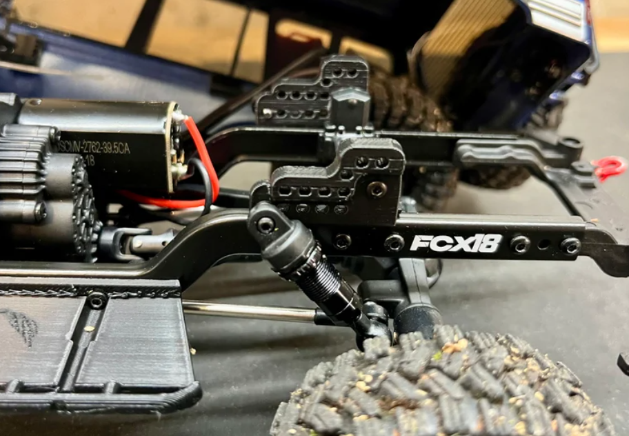
One issue I want to solve is that many of the fasteners on the FCX18 are self tapping into plastic; realistically this isn't a huge concern if you aren't constantly removing and reinstalling parts. However, it can be easy to strip threads by over torquing, and the threads can loosen over time. I designed these shock mounts around M2 threaded inserts to avoid any problems with plastic threads.
One thing to consider with these inserts is that they take up more space than just a 2mm hole; The inserts themselves are 4mm in diameter, and also require at least another mm of plastic to set into.
Many of the existing shock mount solutions are separate pieces for each corner that screw into the stock mount points. The rear of the chassis has alot of room, so I designed a whole new chassis brace / shock mount to replace the stock brace. I modified the brace design to have more clearance for the rear diff but I might have gone a bit overkill with it. I added some ribs for stiffness as the brace design looks a bit floppy, but I've heard that some chassis flex is desirable; I'll have to look more into this later. As designed, suspension travel at full extension will reach the same point as the stock configuration but offer more travel at full compression, with travel increasing as you mount the shock farther inwards.
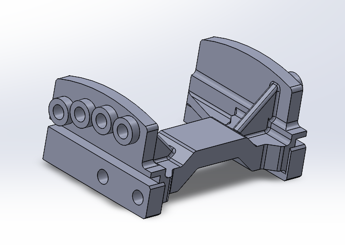
Unlike the rear, the front of the chassis is very limited in space. In order to make a weekend meetup I threw this design together and had it printed out in about 15 minutes, so it definitely has room for improvement. Right now It only has a singular mount point and the tolerances are very poor, but still gives me a bit more travel. A single piece mount/brace like I did for the rear doesn't seem feasible for the front, as the ESC and battery take up a lot of space.
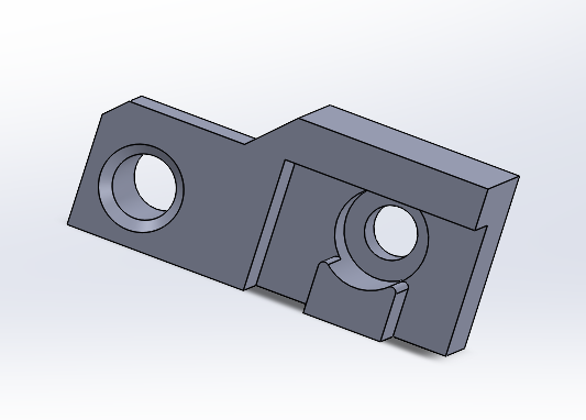
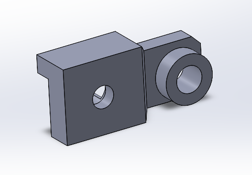
I did a quick coarse print out of PLA and it seems to hold up well. I should have made the fastener holes deeper since the shocks don't fully seat into the mount points for the rear. I haven't done any real analysis or testing, but the rear definitely has more squat now. At full flex (e.g. left compressed and right extended fully) the tires barely rub the edge of the fenders. I had designed in multiple mount points in case the steepest settings had too much travel but the suspension isn't bottoming out yet, so the shallower mount points are basically useless. Looking at the new brace on the chassis, I have a bit more room than I accounted for in the initial design. For V2 I am hoping to have a similar or greater range in compression, and increase the full extension range about 1mm. At some point the links will bottom out on the chassis which could be fixed by buying some high clearance links that are available.
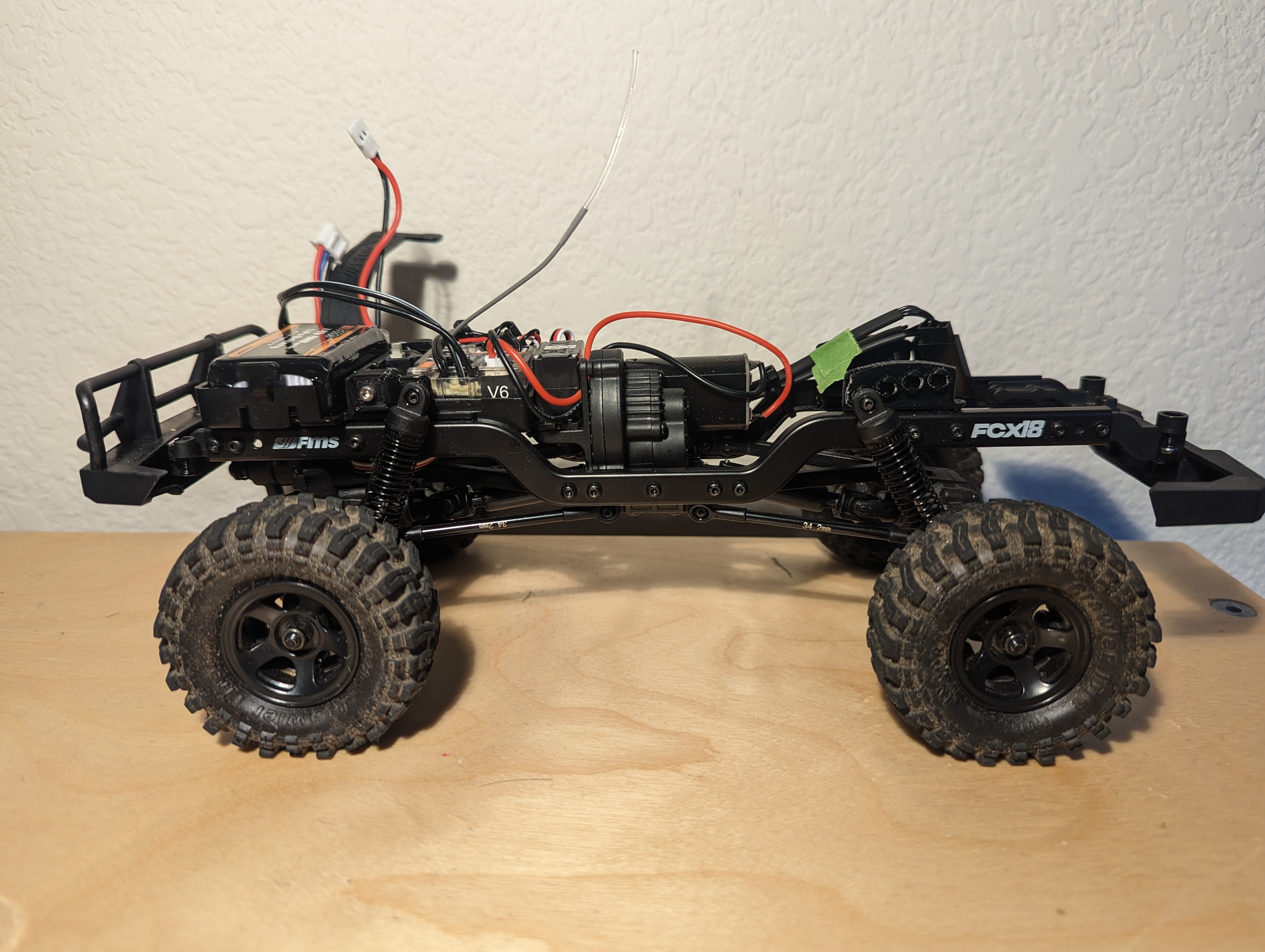
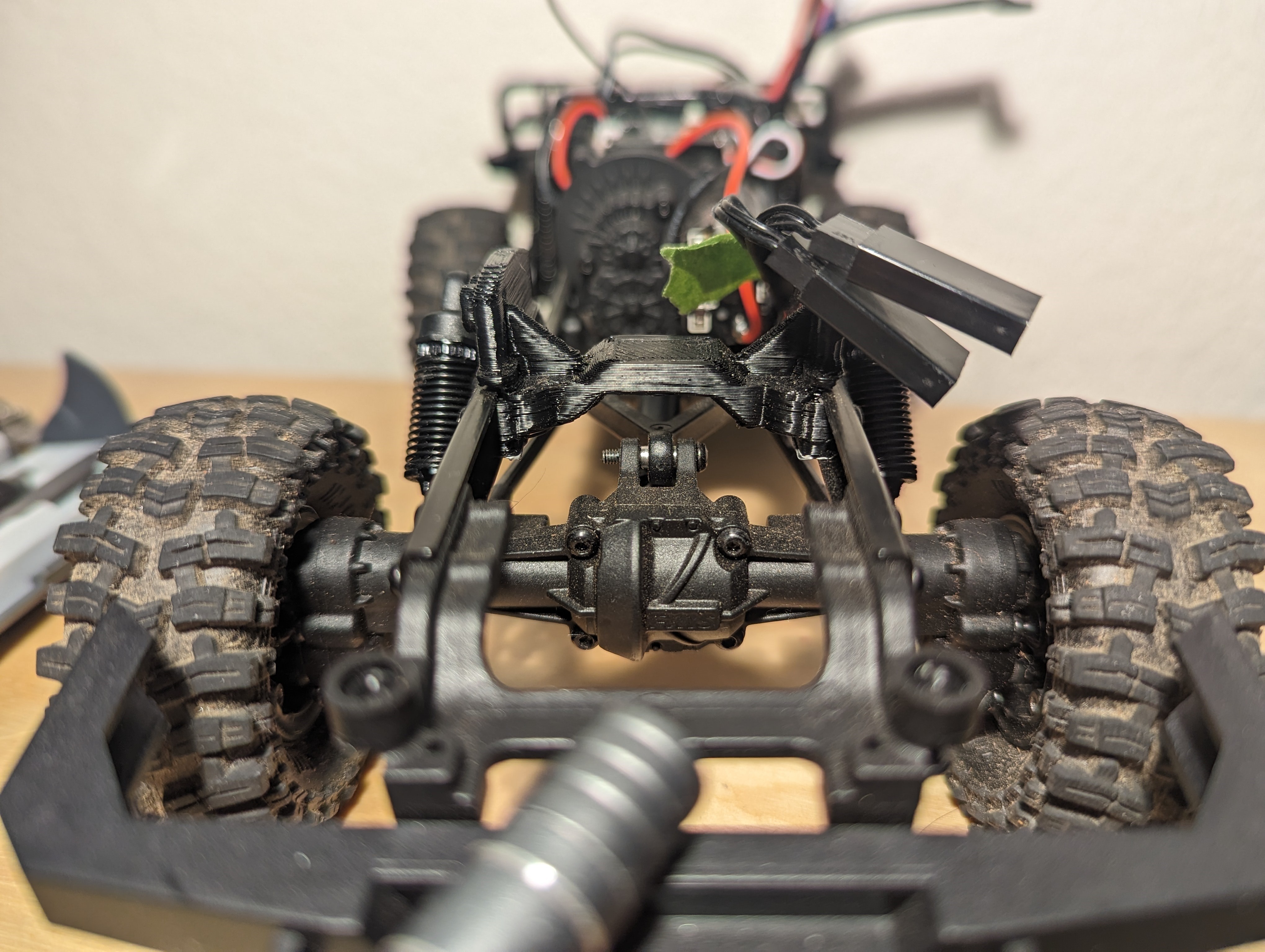
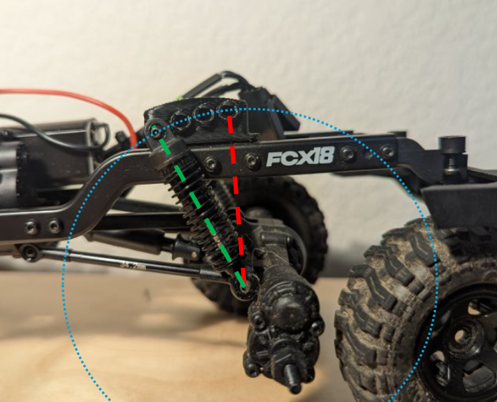
The steering servo hitting the battery tray and existing front shock mount is the limiting factor for how much movement I can get out of the front suspension right now. One of my next tasks is to take apart the battery tray and ESC holder and see if I can somehow optimize the design for front suspension travel, or just open up some more room for new front shock mounts. Another thing I want to figure out is some sort of magnetic or positive retaining clip mount for the body instead of the two phillips and two m2 screws it uses currently. Ideally, the body mounts will allow for a degree of freedom of how high the body is mounted above the chassis. More suspension travel in compression will require raising the body, which will in turn need to be offset by lowering the CG somehow. I'm hoping to find some free lead tire weights to toss in the chassis somewhere, instead of buying all metal diff/portal housings and links. As cool as they are, I have too many expensive hobbies at the moment :)
Discussions
Become a Hackaday.io Member
Create an account to leave a comment. Already have an account? Log In.