To help position the upper shock mount location, I created a simplified geometric model of how the shock should travel based on its compressed and uncompressed lengths and its angle compared to vertical.
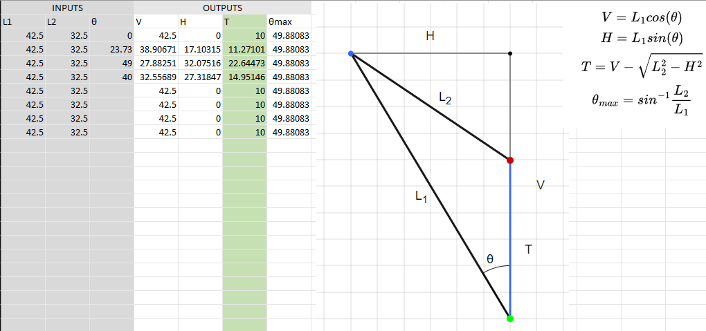
In this case, we are looking at the rear drivers side shock. The lower mounting point is green, and the upper mounting point is blue. L1 and L2 represent the uncompressed and compressed lengths, respectively. For the stock shocks, I measured these to be 42.5mm and 32.5mm, for a shock travel length of 10mm. H and V are the horizontal and vertical displacements of the upper mount when compared to the lower mount. The θmax value is the angle at which your shock will be completely horizontal at full compression. Ultimately, we are looking for the blue line T, which is the total travel you will see from the wheels. In reality, the line of action will be a curve rather than a straight vertical line, but I figured this is a good enough approximation as a better model would be a bit more complex to derive.
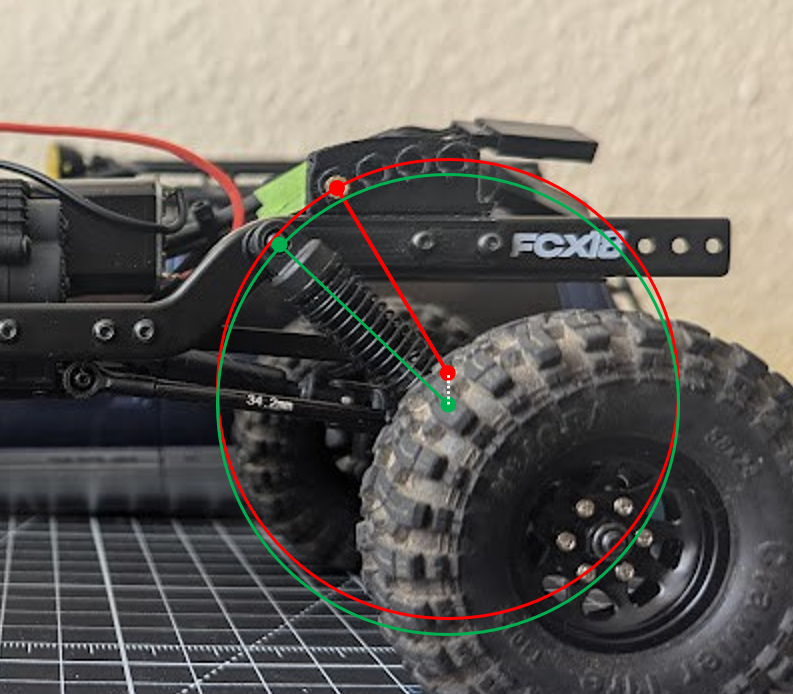
My 'V1' rear shocks had an angle of about 24 degrees, which gave me about 1.25mm more travel. At θmax, we more than double the stock travel length. I wanted to test a setup with around 3mm more travel on extension and 1mm more on compression than my V1 setup, and an angle of about 40 degrees will get me the total travel needed. The 'mount circle' I described in log 1 will be dropped by 3mm to give the extension I want, rather than just increasing compression travel by 4mm. With such a steep shock angle, the spring loses 'effectiveness' in the vertical direction so I don't expect ride height to change significantly.
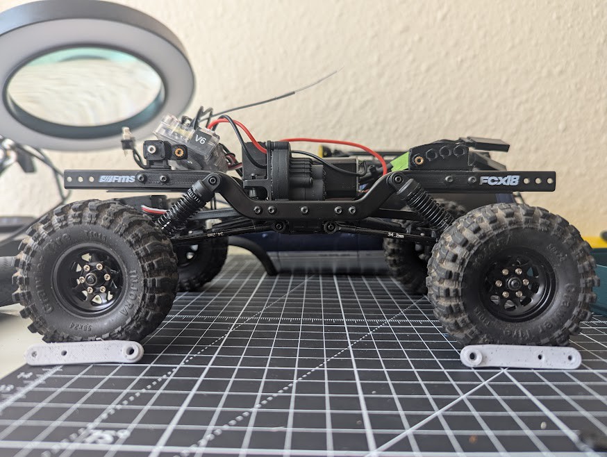
Pictured are the new mounts installed on just the driver's side. The white mounts are there to help visualize how they look a little better. They are only 2mm thick and have a little bit too much flex, but they work as a prototype for now. As currently designed there is not much modularity or adjustability. I am considering a system where there is a "base" that either screws into the frame or is part of the chassis brace, and different "blades" that screw into the base to make it easier to adjust suspension setups. I could do different blades for different heights at full extension, with each blade having several mounts of different angles.
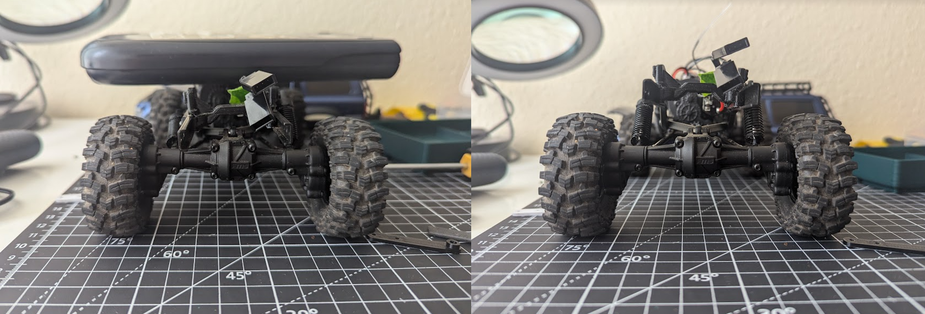
It might be difficult to see from the pictures, but there is a bit more travel on both extension and compression, although maybe not as much on extension as I wanted. I appreciate FMS for making the frames symmetrical. I have been reading that it can be beneficial for crawling to have a stiffer rear and to limit extension travel in the front by means of a center limiting strap or something similar.
The next thing I will work on is making some magnetic body mounts, getting the body on and off is currently a pain in the ass and deters me from taking apart/putting the truck together so I can actually use it!
Discussions
Become a Hackaday.io Member
Create an account to leave a comment. Already have an account? Log In.