 Alana B
For V2 of the MidiCard Plus, I wanted all components to be assembled on the board, instead of having to solder a module onto the MidiCard. I went with the same ATSAMD21G18A chip that the Xiao uses, and followed a few similar SAM D21 schematics to design my own PCB with a USB C connector, a 32.768kHz oscillator, indicator LEDs, and a 3.3v regulator. I had an EE review my PCB and he recommended putting all of my decoupling capacitors closer to the chip.
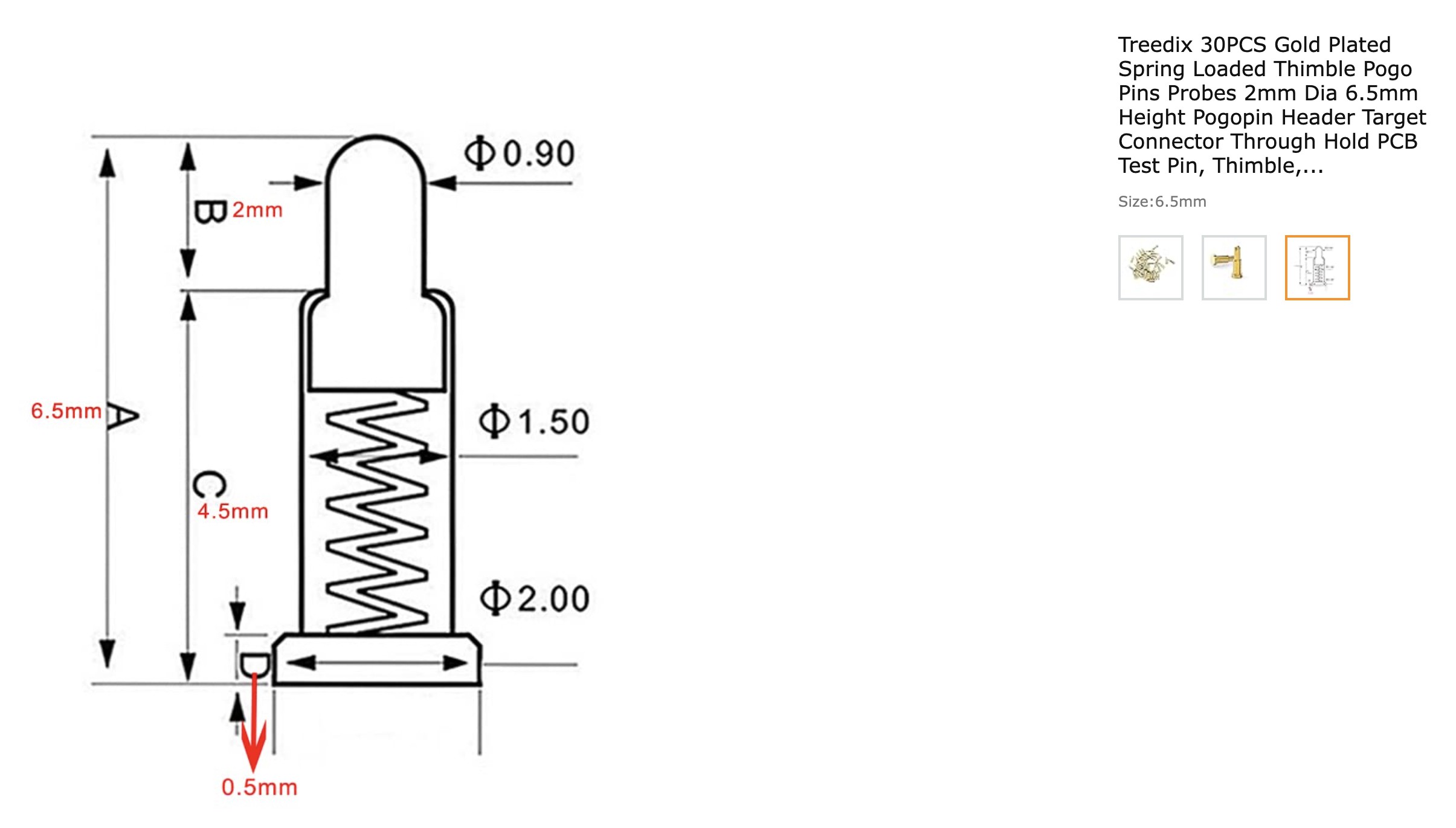
To program the board, I'd still use USB and Arduino, but since the ATSAMD21G18A doesn't come with a bootloader, I'd need to expose the SWD pins to burn the bootloader first, and I purchased an Atmel-ICE in-circuit debugger to program it. I decided to try exposing the SWD pins as test pads, and bought some 1mm pogo pins to connect to them.
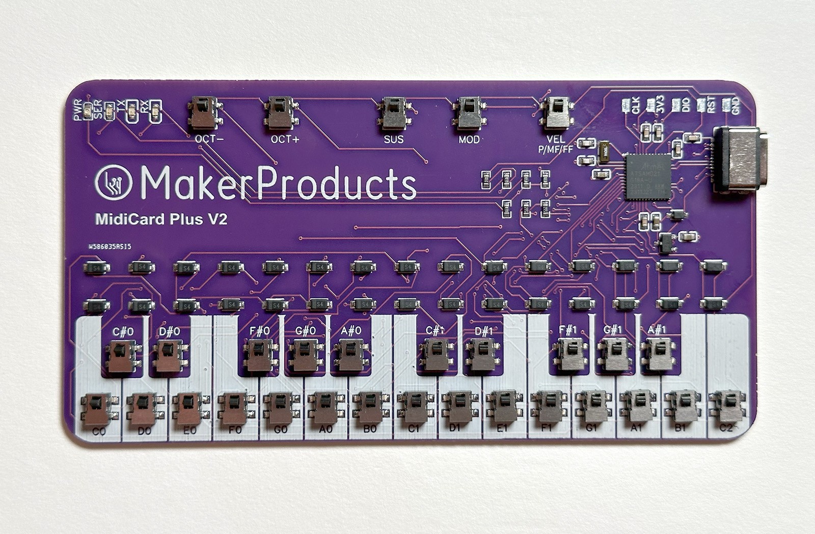
PCBWay graciously offered to sponsor this project, so I ordered my first order through them. They acquired all of the components in my BOM and assembled them, sending me photos to verify the assembly. I added piano keys to the silkscreen to make it more obvious that it's a piano keyboard. The resulting PCBs came out great:
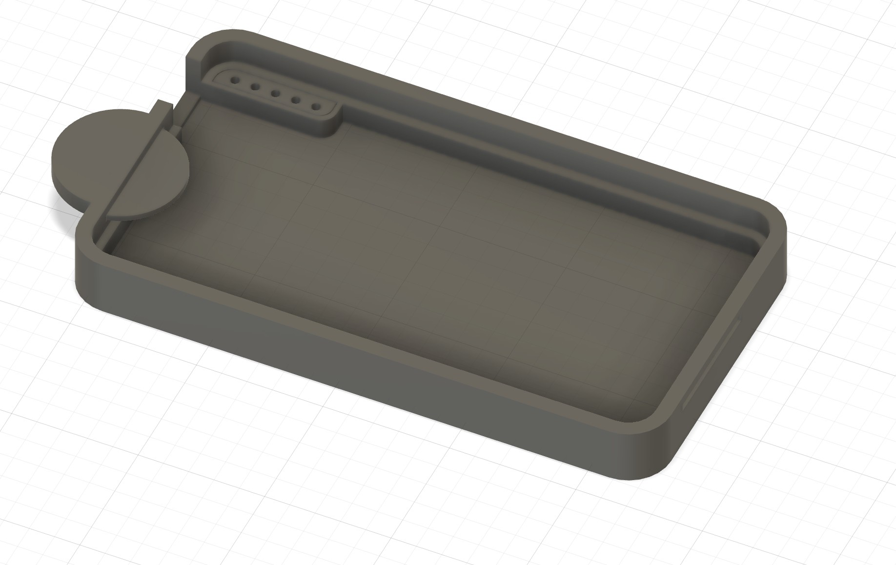
Now it was time to make a dock to program them. I exported a DXF from EasyEDA and imported it into Fusion, flipping it over and then designing holders for the pogo pins and a simple locking mechanism to hold the board face down against the pins. I made the part that holds the pins separate from the housing so that I could iterate on the tolerances of the pins without having to reprint the whole thing. The tolerances for both the housing and the pin diameters was .2mm.
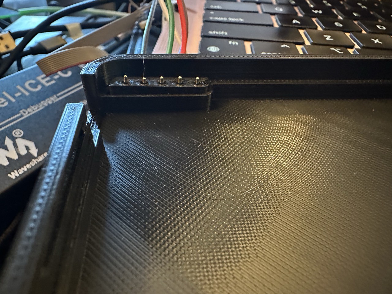
I soldered jumper wires to the pogo pins and installed them in the housing, and surprisingly, the pin connections worked the first time I plugged them in.
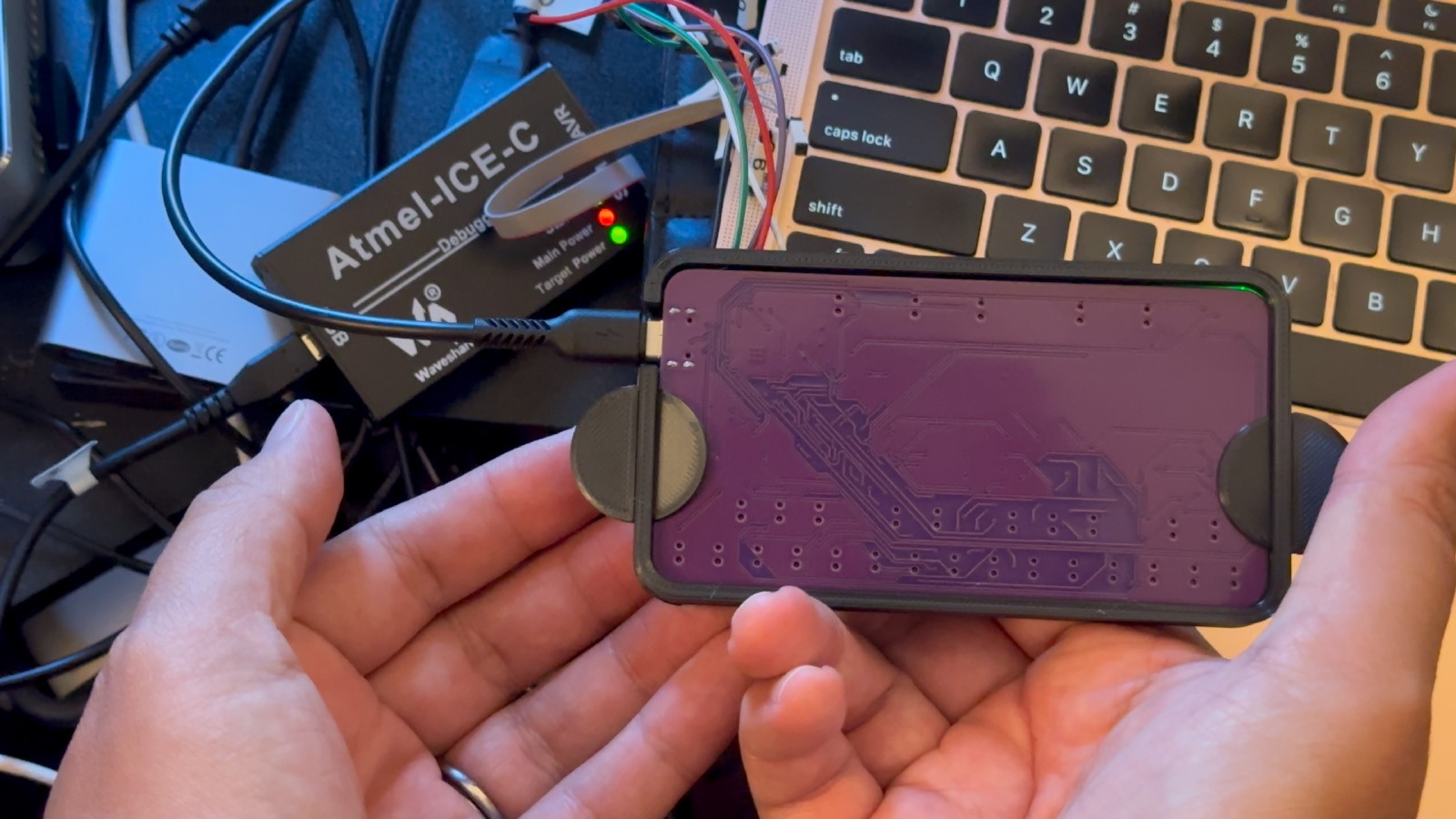
Working with Atmel-ICE and Atmel Studio gave me more trouble. The manual for Atmel-ICE labels pins 1 through 10, but the cable that comes with it are labeled 0 through 9. I wasn't sure if 0 was 10 or 0 was 1. 0 was 1. These are the pin mappings for programming the SAM D21 chip, using the numbers on the wires:
3 - SWDCLK
1 - SWDIO
9 - RESET
0 - VREF (3.3V)
2 - GND
I tried various firmware images to burn to the board. I also had a Sparkfun SAMD21 breakout board that I tried working with as well that was helpful to debug with. ChatGPT was helpful debugging the programming steps with Atmel Studio. Sparkfun's ARM programming guide was helpful as well. The steps that ended up working were:
-Set fuse USER_WORD_0.NVMCTRL_BOOTPROT to 0.
-Program the board with sparkfun's SparkFun_SAMD21_Dev.bin bootloader from their arduino zero UF2 bootloaders.
-Set fuse USER_WORD_0.NVMCTRL_BOOTPROT to 8192 to protect the bootloader.
Arduino still wasn't seeing the MidiCard Plus V2 or Sparkfun dev board after I burned bootloaders to them. I tried the Xiao's firmware and I'm not sure why it didn't work, but for sparkfun's bootloader to work I had to install Sparkfun's SAMD boards library and board definitions as shown in their guide. After that, Arduino saw my board and I could run my code on them. Everything worked!
Next I'd like to use the command line version of Atmel Studio and batch the bootloader and software programming all in one step, so I'll have a quick and efficient programming station.
Thanks to PCBWay for sponsoring this project!
Discussions
Become a Hackaday.io Member
Create an account to leave a comment. Already have an account? Log In.