For more minor details about this doorbell alert light project, check out my webpage: https://www.approachlabs.com/doorbell-alert-light.
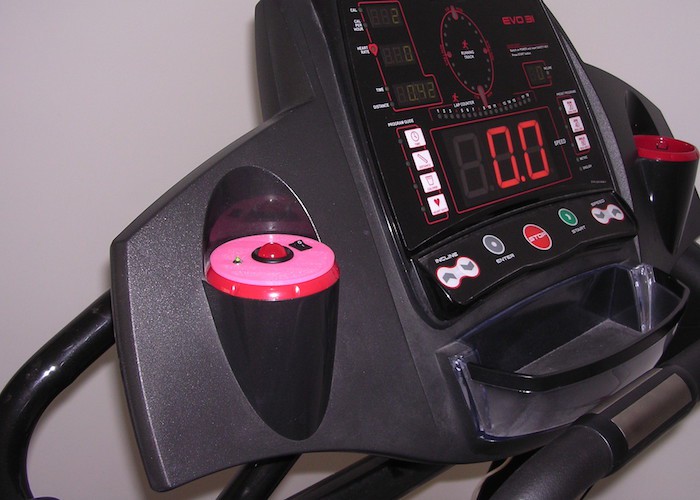
The final assembled device in a 3D printed enclosure:
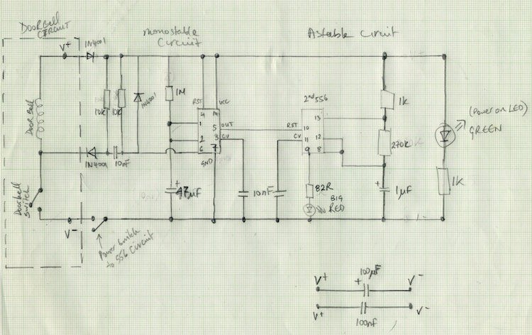
I used one 555 timer circuit to control the length of time the flashing on the doorbell alert light is active for. Another 555 circuit was used to control the flashing light's tempo. Since I needed two individual 555 timers for the device to operate, it made more sense to use a 'dual 555' timer chip, designated the 556 Timer.
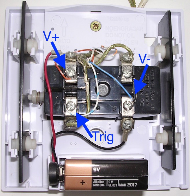
When the doorbell is pressed, the trigger line to the first 555 timer is momentarily pulled to ground activating it. The output from this first 555 circuit connects to the reset pin of the second 555 timer circuit. While the first 555 circuit is counting down its timer, it holds this output line high. This, in turn, holds the second 555 circuit in active mode, allowing it to do its job of flashing the doorbell light.
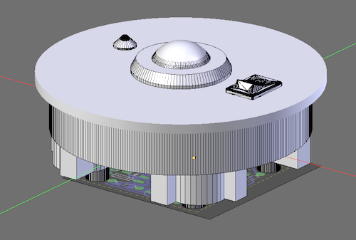
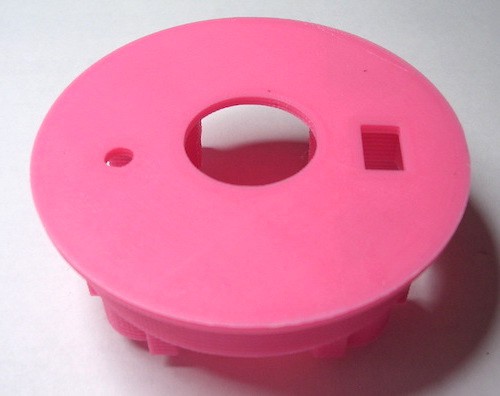
I made the circuit board using a PCB photo-etching technique with a single-sided photosensitive copper-clad board. The PCB had to fit inside a cup holder on the treadmill. This limited it to a size of approximately 45mm x 45mm. The enclosure incorporated a large red 'alert' LED in the middle and a small green 'power-on' LED to one side, as well as the on-off switch.
Finally, I drilled a hole in the bottom of the treadmill bottle holder cup and re-purposed an ethernet patch cable to connect the device to an ethernet wall socket. I had redirected the socket's wiring to terminate at the doorbell box which provided the device with its trigger as well as power.
 Antonio
 DIY GUY Chris
 Hulk
Hulk
 BotFactory