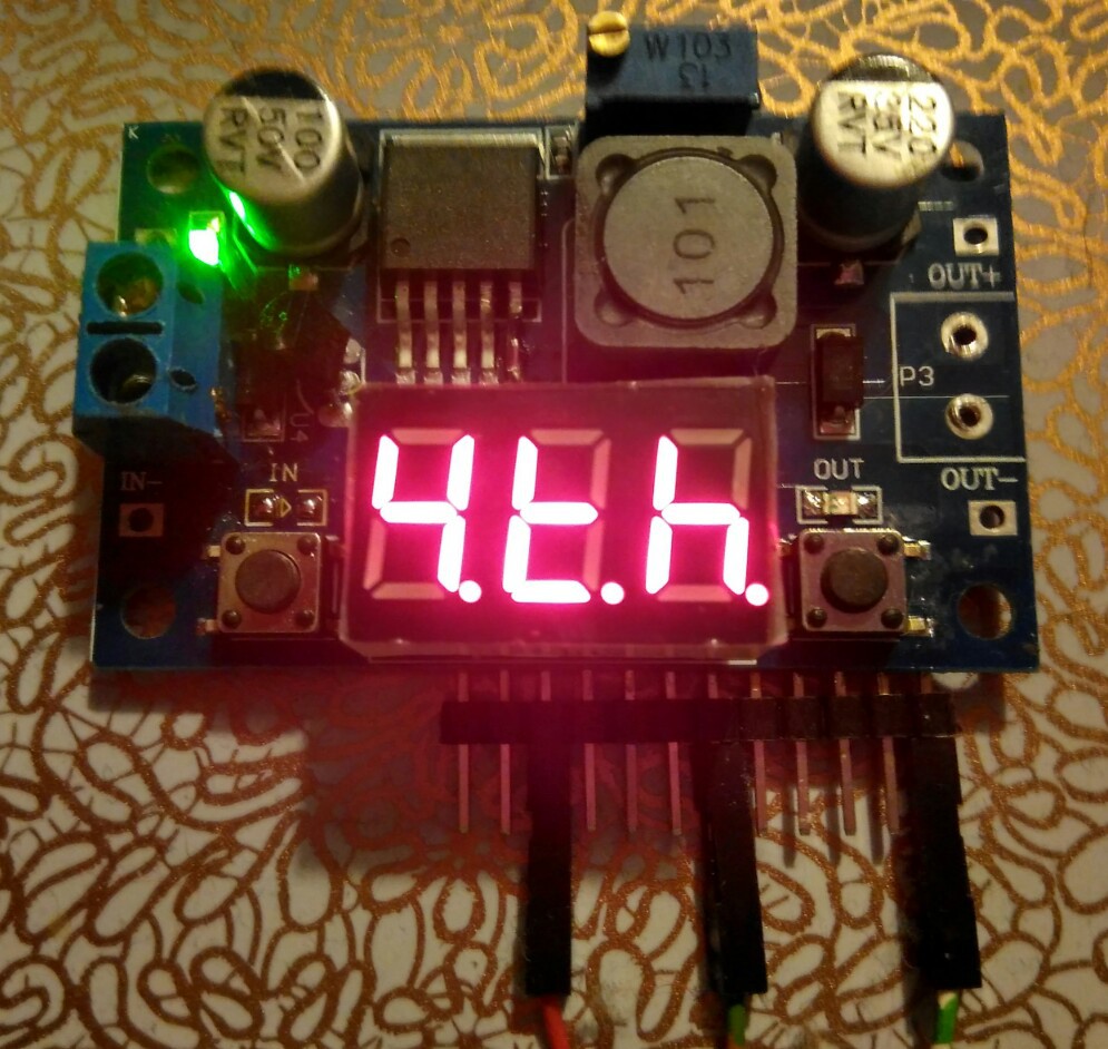
The voltmeter part of the $1.50 DC/DC module uses most of the GPIOs for driving the LED display. Two of the remaining GPIOs are the "voltmeter inputs" and they'll be needed as inputs for control tasks, PB4 will control LED "out" and the !ON/OFF input signal of the LM2596, and PC3, alias TIM1_CH3, a will control the feedback loop of the LM2596 instead driving LED "in".
The board key circuit is a mess (the 7S-LED display has to be blanked while a key is pressed), but that won't be an issue.
Now, what is missing? Yes, the serial interface for Forth console and remote control!  My idea is that it should be possible to convert DC/DC modules without having to remove the 7S-LED display, and using the now unused PB5 isn't an option.
The obvious solution is to use a digit or a segment of the 7S-LED display because soldering a cable to the pads is easy.
The segment that's easiest to live without is DP (PC7), pin 3 of the header in the picture above. I'll find a way to switch between using it for the LED display and the serial interface (most likely using a timeout). Later on, a communication protocol might be synchronized with the LED MPX.
Note that LED "in" has already been removed, and PC3 is connected to a header pin.
EDIT: I tried a 60s timeout for switching back from "serial com" to "display with dot". When the board is in "display mode" the communication is stable after pressing the enter key once. Interactive and non-interactive use cases have now been covered.
 Thomas
Discussions
Become a Hackaday.io Member
Create an account to leave a comment. Already have an account? Log In.