 Kris Winer
-
Finally fixed the BLE Serial API
08/13/2022 at 01:47 • 0 commentsIt's been more than a year since I have spent any time on Rodan mostly because of a persistent problem we have been having with BLE Serial. After start up of the program I would get a few BLE reports and then after a minute or 30 minutes (random but short time) the device would be undiscoverable by a smartphone even though Rodan responded that it was connected and advertising in the USB serial output. Also, the current draw would increase when this weird event (whatever it was) happened. Turns out that this had to do with miscommunication between the M4F MCU and the BLE-managing M0+ MCU (the STM32WB5MMG is a dual core device, M0+ to manage the BLE stack and M4F for application programming). This was corrected by 1) using the latest ST BLE stack (14.0, the original was 10.0) where a lot of bug fixes were implemented by ST and 2) adding some work arounds deep in the bowels of the system layer to correct known and some new errata.
Bottom line is that now Rodan works as it should as long as I use BLE stack 14.0 or later and use the latest Arduino core (soon to be posted at Github). With the device updating sensors and BLE every minute, and logging to flash every two minutes I got 58 hours of run time at 64 MHz M4F+ speed (BLE only works at 32 or 64 MHz) using a rechargeable 120 mAH LIH2450 coin cell battery, so ~2.1 mA average current. This is about what I expected considering that the CCS811 air quality sensor alone uses about 400 uA at the longest 60-second update interval and I am sending BLE Tx data updates every minute.
I could drop the M4F MCU speed to 32 MHz (small savings) and increase sensor, logging, and BLE Tx intervals to try to reduce average power consumption but generally I am at the limit of what I can do and still make the device useful and practical (i.e., waiting 1 minute for a BLE update is already a pain...longer would be intolerable). BLE Tx is the main power user here, although turning off the CCS811 would save a lot of power too, but then air quality is pretty interesting data, no?
I'll keep these intervals to use as a baseline. Fussing about reducing the power Rodan uses below this already-low level can wait. Instead, I want to know what it takes to keep Rodan going indefinitely via solar charging, which was one of the main design goals.
So next is to test operation of the solar cell in charging the 120 mAH coin cell battery. I would need to develop about 50 mAH per day in order to keep the device running indefinitely. I previously measured ~7 mA charging in direct sunlight using the 50 mm amorphous silicon solar cell I plan to use for Rodan, meaning I would need to have the device exposed to direct sunlight for seven hours a day (or use a bigger battery and/or solar cell!).
This is not going to happen on my back deck or in my front garden (where I could conveniently receive BLE Tx in my home), which gets about 4 hours of direct sunlight a day but could happen if I mounted Rodan on the one part of my 2 acres that gets the most sunlight : "the peninsula", as I call it.
I'll start with the garden and see how much more than 58 hours of 120 mAH battery lifetime I can squeeze out of the available four hours of direct sunlight. If I use ~50 mAH per day and generate ~30 mAH per day my net usage would be 20 mAH per day, so I might just manage almost a week of garden logging data this way...TBD
-
Same Idea, Different Implementation
07/30/2021 at 22:17 • 0 commentsIt's been a while since I updated this project. In the meantime, we have been developing tools to make use of ST's relatively new line of BLE-enabled MCUs: the STM32WB55. We developed basic hardware designs including a development board (Firefly) and a modular wearable (Katydid) using the discrete version of the STM32WB55. Designing with the STM32WB55 is straightforward but a bit complicated with an external SMPS circuit for lowest power usage, dual crystals, and an external matching chip and external antenna for the BLE.
With the introduction of the STM32WB5MMG BLE module, all of this is integrated into a small (7.3 mm x 11 mm) package with 68 GPIOs, 1 MB of flash and 256 kB of SRAM and everything is included. The package is 0.435 mm pitch LGA and takes some care to mount but is straightforward. There are also some constraints on where to mount the module on the pcb for best performance. But we have used this module on 15 mm x 20 mm devices for consumer product research and on a 50 mm x 20 mm "Acoustics Lab on a Stick". Range and/or efficiency might suffer with "improper" placement but the BLE and MCU work pretty well regardless...
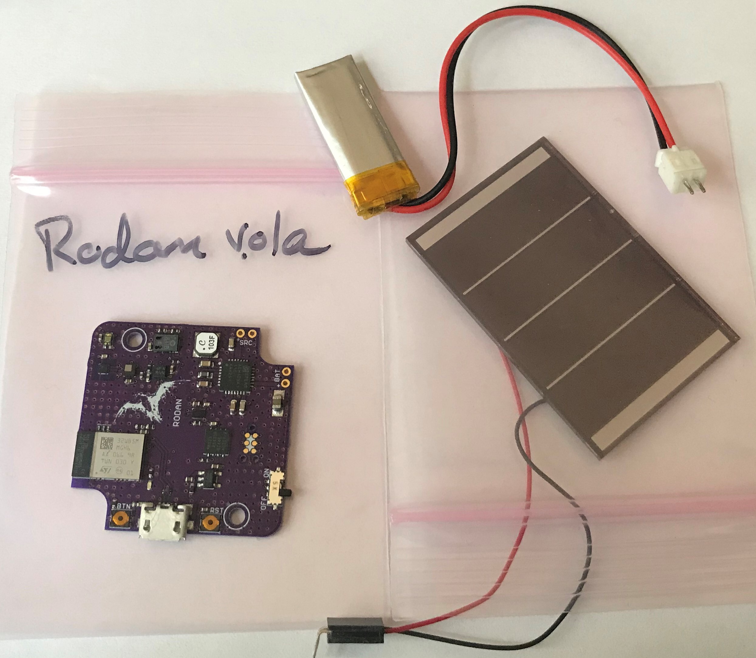
So it is natural I would indulge my interest in environmental sensing by using the STM32WB5MMG as the heart of a new "Sensor Tile" design. I call it Rodan:
![]()
![]()
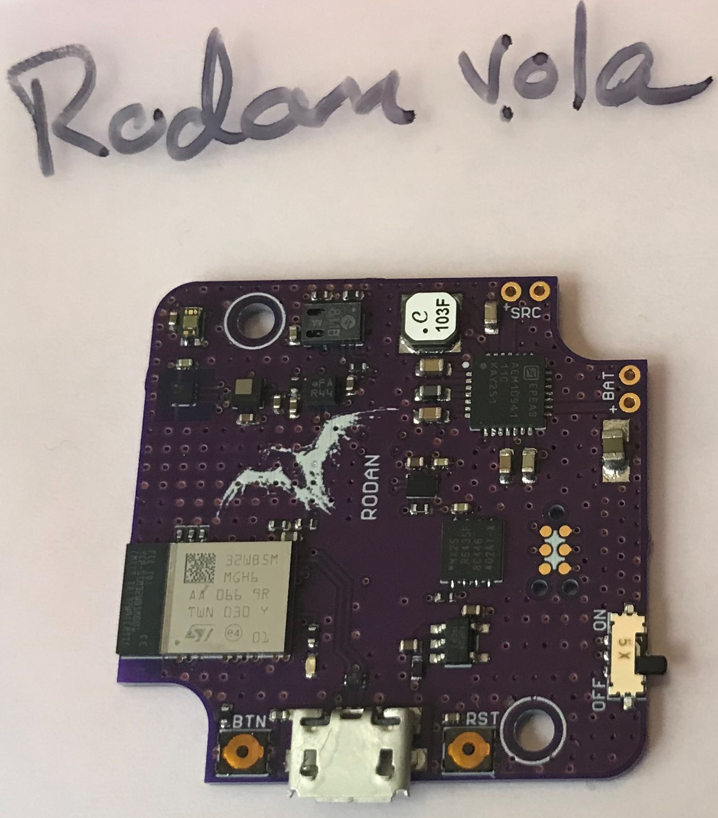
The 34.5 mm x 34.5 mm pcb is designed to mount into a blue transparent Hammond 1551-Q box. The STM32WB5MMG module with integrated pcb antenna is lower left. Programming is via USB (or tag connect) and the Arduino IDE using Thomas Roell's excellent STM32WB system layer and Arduino wrapper.
The board can be powered via USB and there is a switch-enabled 300 mA MCP1812 LDO for the purpose The board can also be powered by the AEM10941 HVOUT (3V3, 80 mA) when there is an AM-5412CAR solar cell source and 100 mAH LiPo battery attached. The idea is to program the board via USB (my preference) and then deploy outside with just solar cell and battery with the sensors collecting and storing data on the 8 MByte MX25R6435FZAI QSPI flash for ~six months or so.
The sensors include the VEML6040 RGBW light sensor, LPS22HB barometer, HDC2010 humidity and temperature sensor, BMA400 accelerometer for motion detection, and the CCS811 for eCO2 and TVOC estimation. There is also an LC709204 battery fuel gauge for battery voltage and percent remaining charge monitoring, etc.. So this makes six I2C sensors and six interrupts to manage.
The strategy is to keep the STM32L4 component of the STM32WB55 dual core in low-power stop mode as much as possible only waking up on interrupt, either sensor data ready, battery alarm, RTC timer or general timer interrupts for logging and for sensors like the VEML6040 that have no interrupts.
I have one device assembled and I have verified that everything is working. I wrote a sketch to configure and manage the sensors and log data at such a rate that I can keep the device going for six months before the flash fills up. This is worth a bit of discussion.
So the flash has 32767 256-byte pages. I have broken each page into 8 sectors of 32 bytes each and I am writing the essential data from all of the sensors including a time and date stamp using these 32 bytes. I am not capturing the accel data since I do not expect the device to be in motion when deployed, at least at first. I am capturing the InMotion flag (byte) though so I can tell when the device fell down or someone messed with it. This means that I can capture 32767 x 8 data samples, which at once per minute is 262,132 minutes of data, or 182 days of data.
I still need to add BLE NUS so I can periodically check on my device with a smart phone and I need to measure the average power usage to have some idea how much battery margin I have. I expect ~30 mAH of power generation now at the height of Summer ( ~4 hours at ~7 mAH/hour in ~16 klux light) but this will decrease with the approach of Winter and I am not sure if the device will make it through the entire six months. This will depend somewhat on where I place it, of course.
I will make a trial run over a week or so to make sure everything is working as I expect and that there is no show stopper before letting it go for months. I'll report once I recover the device and plot up the weeks worth of data.
-
Longer Test of the Sensor Tile
09/23/2018 at 23:32 • 0 comments09/23/2018
As part of my test of using a small solar cell and the BQ25504 breakout board to power an environmental data logger (using the SensorTile v.01g as a vehicle) I collected about six weeks worth of data. This is the longest stretch of data I have obtained to date. I am still not quite sure what to make of it. The data recorded on SPI NOR flash consists of ~11,000, 256-byte pages representing time and date, pressure, temperature, humidity, RGBW ambient light level in lux, eCo2 and TVOC air quality data, 3-axis acceleration, and battery voltage and state of charge. It's a lot of data for my free Open Office spreadsheet to handle and it is somewhat painful to produce graphs and analyze this much data with this free tool. I here Excel is better in this regard, but pricey.
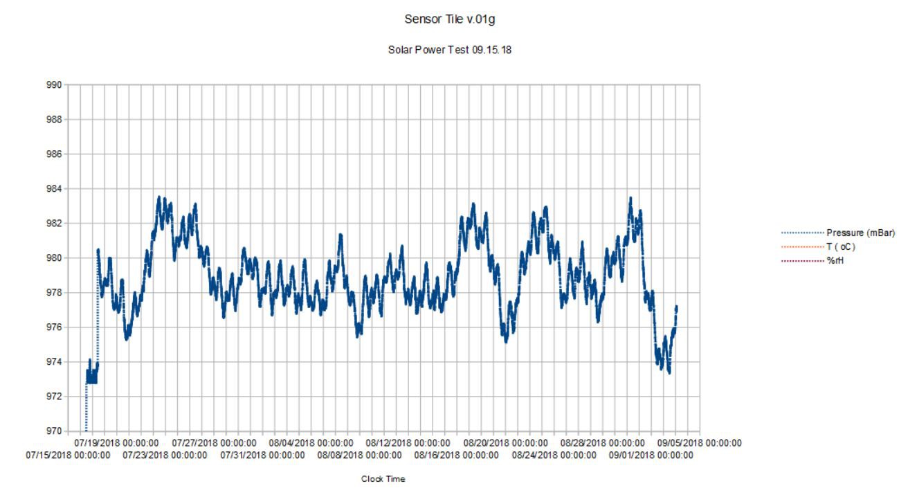
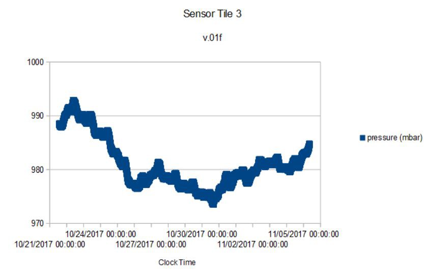
Here is a small part of the data I managed to plot. First the pressure from July 15 to September 5, 2018:![]()
The first two weeks in August had remarkably steady air pressure; it wasn't until beginning of September that the pressure dropped significantly below Summer trend with the onset of somewhat cooler weather.
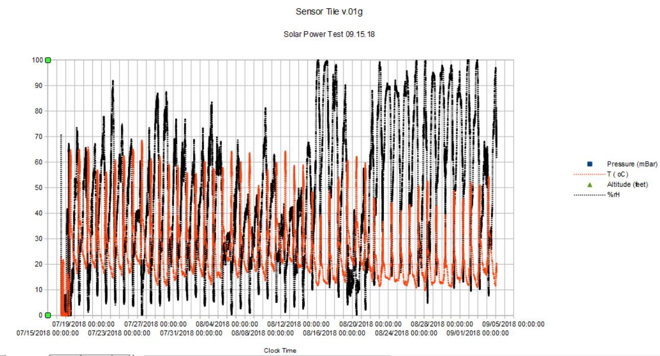
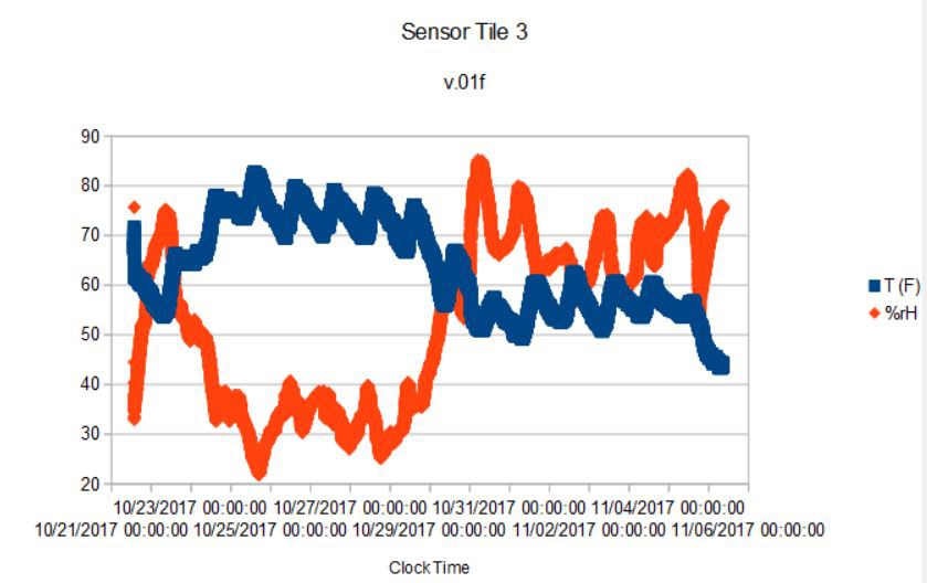
![]()
Here I am plotting the temperature (orange) in degrees Celsius and humidity (black) as relative percent. The device was placed in a glass jar and exposed to direct sunlight for a few hours a day (needed to generate power from the solar cell). Thus the temperature is somwhat unreliable due to the heating by direct sun exposure. Correspondingly, the humidity drops when the temperature rises (that's just how the sensor works). So in direct sunlight the temperature and humidity data are unreliable to say the least.
Interestingly, during the time the pressure remains in a tight band (first two weeks in August) the humidity is rather low, rarely breaching 80% even in the depth of night. And as the pressure starts to increase in variation around August 16 so too the humidity regularly reaches >90%; in other words, the data can detect a clear change in the weather pattern as well as the diurnal variations one would expect.
Best practice for the next test would be to mount the solar cell and Sensor Tile apart from each other, obviously. Likely with the solar cell mounted on top of an open-bottom container with the Sensor Tile protected from the elements and direct sun and the solar cell exposed to direct sun.
The only reason the SensorTile data was interrupted shortly after September 5 is that the humidity became saturated causing the BME280 to stop functioning (presumably by shorting VCC to GND) and the Sensor Tile MCU stopped even though the battery had plenty of charge left. This is a know problem (or at least I have seen this before) and I hope partially protecting the Sensor Tile inside of a container will prevent this from happening in a future test. We'll see.....
-
Boost converter for longer device life
12/21/2017 at 23:47 • 0 comments12/21/17
Well after several months of struggling to get the average power usage down on the SensorTile to ~900 uA with both BLE and the CCS811 Air Quality sensor active, I decided to take a different tack and see what I could do with a larger battery. I didn't want to just do the obvious and literally increase the 4.2 V LiPo size to 2000 mAH, which would clearly let me run the Sensor Tile for ~ 2000 hours. Too easy!
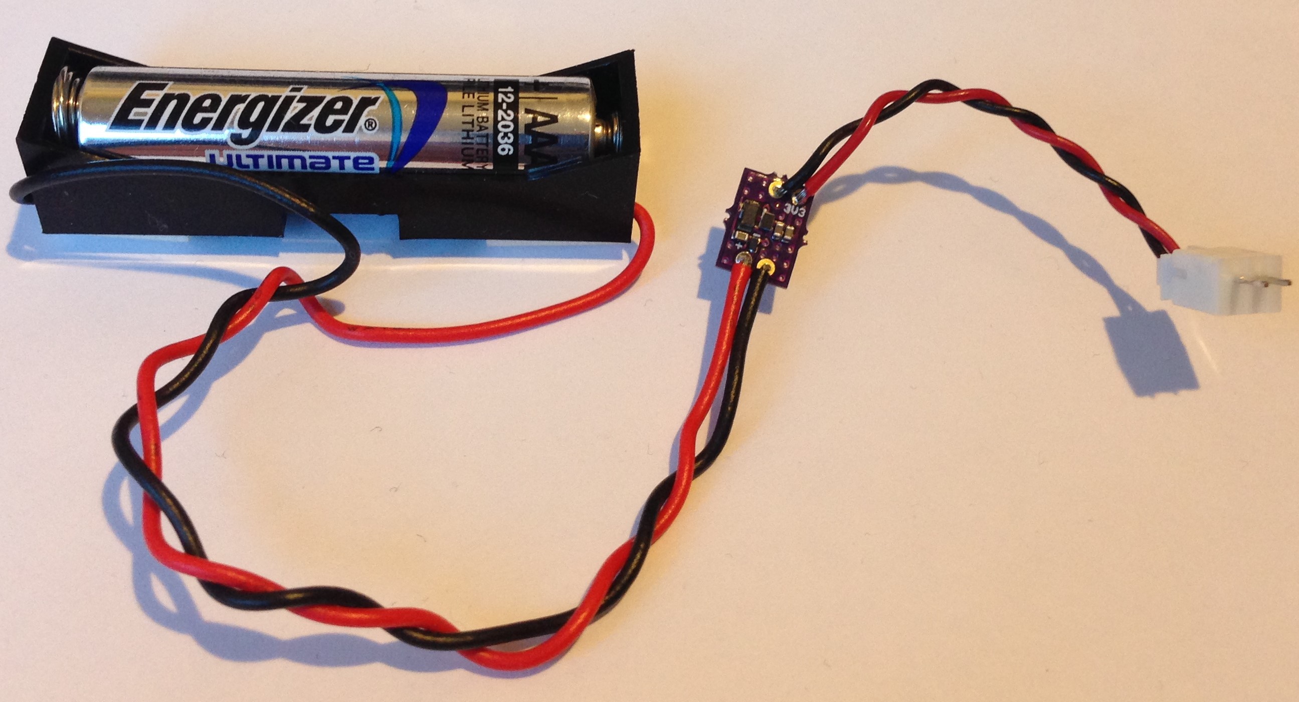
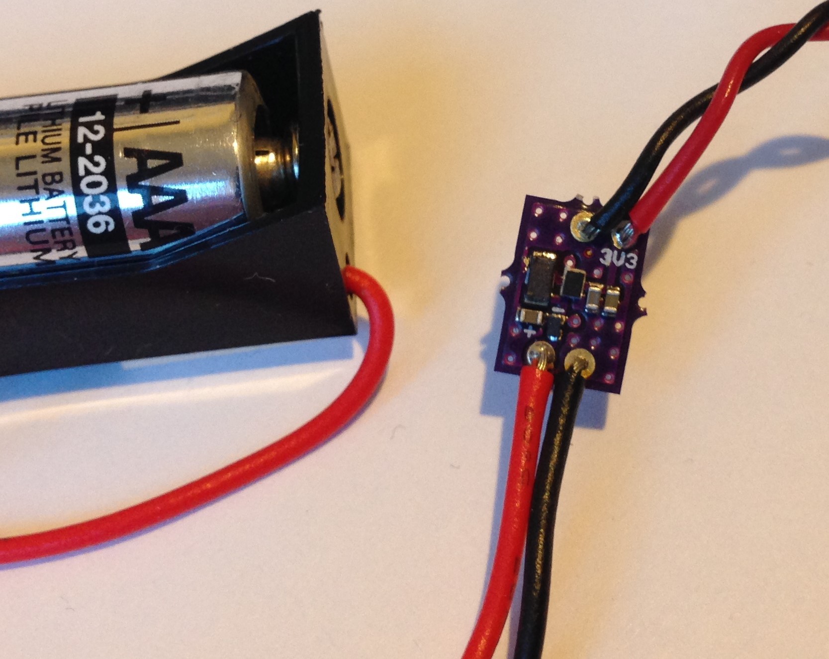
I decided to try using an efficient boost converter instead so I could run the Sensor Tile on a single AAA battery, which has a typical capacity of 1200 mAH but only at 1.5 V or so. I chose the TPS610995 made by Texas Instruments which is a tiny WLCSP that is perfect for this application. It accepts voltage from 0.7 to 5.5 V, boosting anything less than 3.6 V to the fixed 3.6 V output I chose (several outputs are available) and passing unmolested any input above 3.6 V so a LiPo could still be used as the source.
I made a small breakout board for the TPS610995, soldered it to a AAA battery holder and soldered the other end to a JST connector and now I have a power source for the Sensor Tile that accepts any AAA battery and should power the Sensor Tile for about 1000 hours (~85% efficient at 1 mA).
![]()
![]()
I redesigned the Sensor Tile to make a variant the does away with the battery charger and voltage monitor and adds the TPS610995 as input to the NCV8170 LDO and submitted to the fab. This means I will be able to choose to use an AAA, AA, LiPo or just about any battery source from 0.7 V to 5 V and the system will work. Pretty convenient.
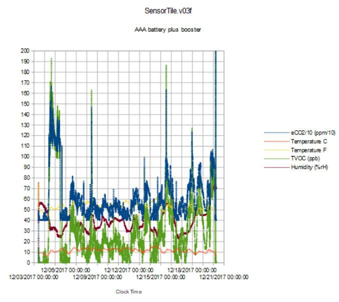
In the meantime, I used the TPS610995 breakout above to retest v.03f of the Sensor Tile since I know it uses ~900 uA of current from previous testing. I placed the SensorTile in its Bud box as usual and then under the portico of our driveway, where it is somewhat protected from the elements but still outside. I expected to get ~40 days of data out of the AAA battery and I adjusted the flash write frequency to once per minute to align the battery duration with the flash capacity. I am somewhat disappointed to find it stopped working after 18 days :<
Here is some of the data that was collected:
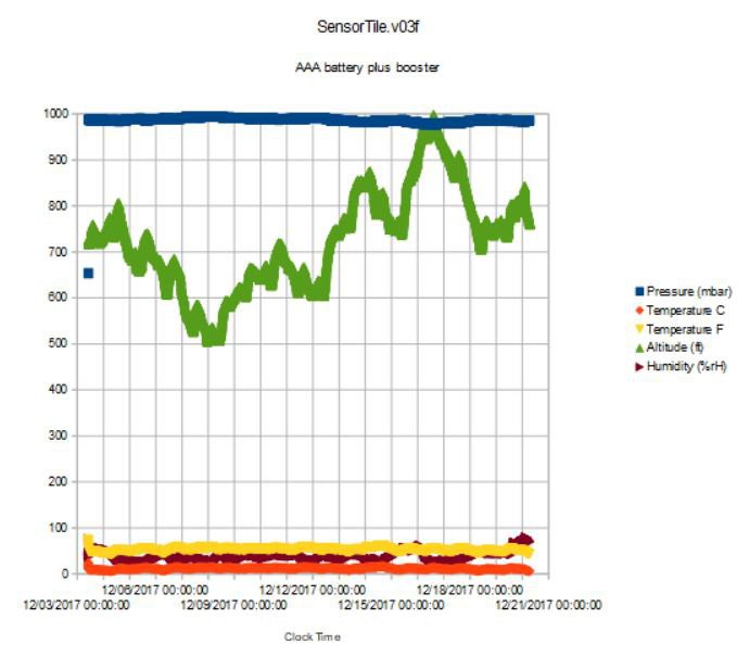
![]()
First pressure, temperature and humidity over the 18 day period. The altitude is a more interesting proxy for pressure and shows large variations and large deviations from the "normal" at our 1050 feet elevation; the pressure was uniformly higher than normal, sometimes much higher (like on 12/9).
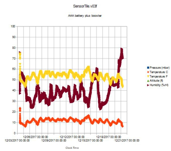
![]()
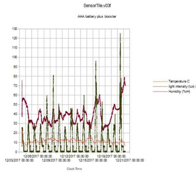
Here is the temperature and humidity at a reasonable scale. The rapid humidity rise and temperature drop at the end of 12/19 shows a clue to the abrupt ending of the experiment; it rained in the early morning of 12/20 and, I suppose, one or more sensors got too wet to function. In fact, the last reading of the CCS811 air quality sensor was pegged at its maxima, a likely culprit.
![]()
There are large excursions and spikes in the air quality data, not sure what the cause of the latter is yet. It is interesting that the eCO2 estimate and the TVOC estimate are not simple scaled versions of one another; they are conveying different information as far as I can tell from this data plot.
![]()
Lastly, the ambient light intensity is more or less as expected but what could account for the 4x variation in the daily maxima in a shaded location? And odd that the peak is just before the midnight storm. And more curious, the highest light intensity spikes coincide with the spikes in the eCO2 data; is the sun or sun's reflection briefly shining on the Bud box on these days?
I think I will try again with a fresh AAA battery and some additional protection from the weather. I suppose for outside deployment, the latter deserves a bit more thought.
-
Lower power with CCS811 at 50% duty cycle
11/15/2017 at 05:10 • 0 comments11/14/2017
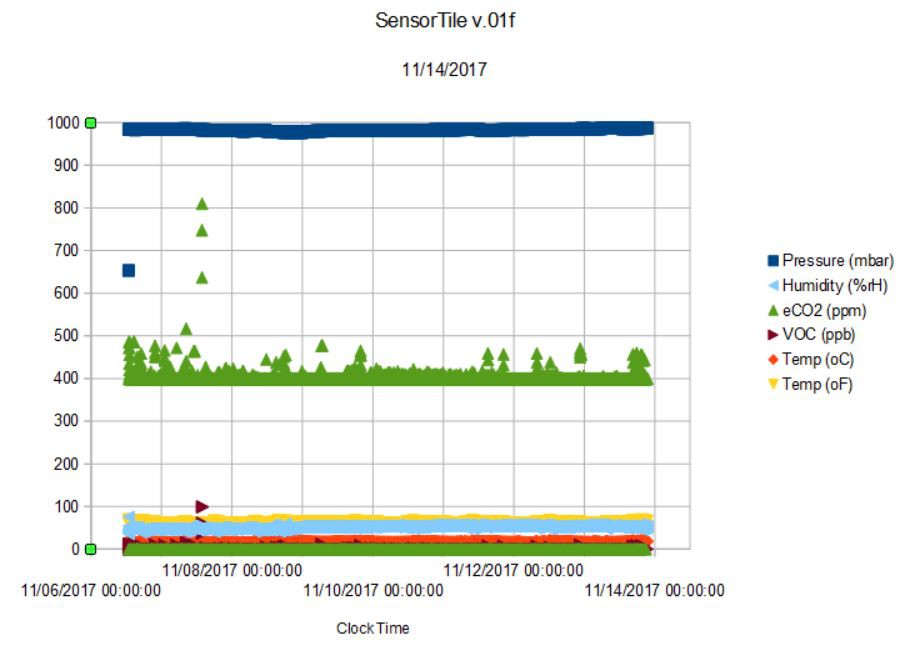
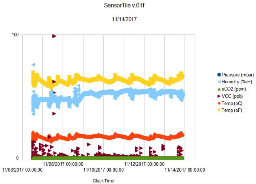
I ran the latest experiment using the same Sensor Tile as I used in the previous log, so it doesn't have the low-power battery charger yet. I modified the sketch to put the CCS811 in idle mode for twenty minutes, and then run in Mode 3 (continuous measurement at once per sixty seconds interval) for twenty minutes; so a 50% duty cycle. I expected this to save half of the 550 uA that I previously measured for Mode 3 or ~275 uA, but it also should saved half of the 200 uA that the CCS811 would ordinarily use keeping the heater on and membrane warm between measurements. So overall, I expected to cut the average power usage by ~375 uA. In fact, using a fully charged 105 mAH LiPo battery the experiment ran for 177 hours (seven plus days) for an average power usage of 593 uA, about what I expected.
The downside of using this strategy is that the heater has to restart every twenty minutes and the air quality data doesn't become reliable until near the end of the twenty minute active period. I wasn't sure what kind of response to expect but the data looks like the sensor is still able to measure meaningful data even at this erratic pace:
![]()
![]()
More than half of the air quality (eCO2 and VOC) data points are zeroes but the data do register excursions in air quality that seem reasonable. For the first three of the seven days I was having some windows replaced and the repairmen were in and out of the house (I kept the Sensor Tile indoors in the main hallway). This shows as larger and more frequent variations in eCO2 and VOC. There is a particularly large excursion after noon on the second day. I am not sure what caused this.
So the verdict is still out whether this is a sensible way to measure environmental data. It certainly saves a lot of power, but I need a better test of the impact on air quality data fidelity. Perhaps a second test with the Sensor Tile placed in a sheltered spot out of doors.
-
SensorTile3: Continuing Evolution
11/06/2017 at 02:28 • 0 comments11/05/2017
It's been two months since the last log entry and the Sensor Tile has gone through another redesign iteration since then. I changed the size of all of the passive footprints and made them smaller to ease assembly and I replaced the SDA/SCL exposed at the board edge with the BMD-350 SWD port to enable replacing the Rigado firmware with my own in an attempt to lower power usage of the BLE module. Turns out this is really not necessary, at least not yet. I'll get back to this point in a second.
I started with several tests of the new Sensor Tile being powered via a BQ25504 and a solar cell. I redesigned the BQ25504 to tighten up the specs and ended up wasting a lot of time because the battery would get to about 50% of the full charge and the entire Sensor Tile would stop working because the BQ25504 undervoltage threshold was too high. So I gave up trying to perfect the BQ25504 and went back to the previous design which worked just fine, but I still had some problems getting the full use of the LiPo battery. Since the number of hours of sun dropped to less than three in my testing area I went back to simple power usage tests using just a LiPo battery. In the first attempt at this rain stopped the experiment after twelve days and in the last attempt I finally got a complete experiment and was able to measure the average power; it only took two months of fooling around to get there.
The results are five hours shy of fifteen full days of running on a 350 mAH LiPo battery. This represents an average current of 987 uA, which is significantly less than in previous tests for a couple of reasons. Firstly, I turned off the microphone; I still haven't figured out how best to use this in an environmental data logger. I also took advantage of improvements to the STM32L4 Arduino core which takes care to properly put unused GPIOs in a hi-Z state to minimize power usage. I also started disabling the SPI just after writing to the SPI flash and enabling SPI just before. Likewise, I put the SPI flash into its deep power down state unless writing data. Lastly, I started using forced mode for the BME280 to get a data reading just once every ten seconds. In other words, I fussed over every uA and looked for ways to cut power while still recording all the data (except audio) every ten seconds.
Here is some of that data:
![]()
![]()
Turns out 15 days worth of data, 42 bytes every ten seconds, is a lot of data, 109500 lines of spreadsheet in fact and it takes quite some time to process this even on Windows 10 and an Intel i5 core. Fifteen days represents only about half the data the 8 MByte SPI flash can record, so as I continue to drop the average power the flash capacity will become better matched to the 350 mAH LiPo battery lifetime (yes, both arbitrary with different data write frequencies and battery size).
It is interesting to see the diurnal variations of the data as well as the longer term variations of trend. It got significantly cooler after Halloween as a weather front moved into the area; the data nicely capture the end of our Indian summer.
This < 1 mA average power usage included broadcasting pressure, temperature, humidity, eCO2 and VOC as well as battery voltage and % charge remaining every ten seconds via BLE. I thought the BLE module was the big power hog on the Sensor Tile 3. But I measured the CCS811 average power to be 550 uA in a previous log so that now it seems it is the air quality sensor that is the dominant component even though I am using the "low-power" pulse setting reading CCS811 data once per minute.
Of course, I could just disable the CCS811 to save power but I really like having the air quality data. One thing I will try is to put the CCS811 in idle mode for, say, an hour and then let it run twenty minutes; a 25% duty cycle, which should save ~330 uA but still provide useful air quality data, which like pressure doesn't change that rapidly. Maybe a 50% duty cycle would be better; there is always a tradeoff, of course.
I discovered in an unrelated project that the MAX1555 battery charger I am using on the Sensor Tile3 is using ~75 uA even when there is no USB connected. I should have checked this before but it is only relatively recently that I have become a maniac about every little uA. The next version of the Sensor Tile is already at the fab with the MAX1555 replaced with the STBC08, which I measured to cost only 2 uA. So even doing nothing differently with the CCS811 using the new Sensor Tile I should expect to be close to 900 uA average power usage. This also means that at 550 uA for the CCS811 (once per minute low power mode), the rest of the components, including the BMD-350 BLE module, cannot be using more than ~350 uA. In other words, the BMD-350 running with stock Rigado firmware is pretty power efficient after all.
-
SensorTile3
09/04/2017 at 22:33 • 0 comments09/04/2017
I finally got the pcbs back from OSHPark with the latest useful changes and a corrected error and put one together this weekend and was pleasantly surprised that everything worked the first time. Always nice.
I moved the BME280 to the back of the board along with the CCS811 so these two "air breathers" could be shielded from sunlight hitting the VEML6040 on the board front. I also got rid of the resistor divider for monitoring LiPo battery voltage relying on the battery voltage, state-of-charge, and charge rate measured by the MAX17048 fuel gauge. I used the analog pin freed up for the orange indicator led that used to be on pin 13 (SPI flash CLK) to allow indication (in this case on for 10 ms whenever the SPI flash page is written --- once every sixty seconds). Lastly, I replaced the 1 MByte SPI NOR flash with an 8 MByte SPI NOR flash for what should be ~24 days of complete, continuous data recording at 0.1 Hz.
I also redesigned the BQ25504 solar cell LiPo battery charger by resizing the resistor network to tighten the under- ( 3.27 --> 3.58 V) and over- (4.27 --> 4.15 V) voltage thresholds as well as changed the layout to conform to the reference design in the datasheet. I also got rid of the battery OK led on the board. This is useful for indication of proper charging but is really not appropriate for a ultra-low-power system.
Last improvement was to take advantage of inexpensive plastic boxes for packaging the whole system in a more convenient and more permanent mounting. The plastic boxes from Bud Industries are perfectly sized for the solar cells I am using and I even made a small hole to expose the VEML6040 to more direct sun to get a more accurate correlation between charging and incident light. For mounting the Bud box on the pole, the solar cell on the outside of the Bud box, and the SensorTile3 on the inside of the Bud box I used pieces of VHB foam tape; a very handy addition to any maker's tool kit!
![]()
Overall, the system is a lot closer to a deployable environmental sensor than it has ever been. I want to make sure the new BQ25504 design performs properly and that I can make use of the data on the SPI flash. No reason to think these won't work but it is always prudent to test a new (or newly revised) design just to make sure. So after the test results are analyzed it will be time to put one or more of these devices out into the wild (we live in the middle of an oak forest) and see what can be seen... and smelled... and heard.Even this last shake-out test is happening at an opportune time since there is a wildfire somewhere nearby producing waves of smoky, stinky air that ebb and flow as the wind shifts; a good test for the CCS811.
-
Using a Solar Cell Charger...Part 3
08/14/2017 at 16:43 • 0 comments8/14/2017
Got a break in the fog so I resumed my solar cell charging experiment with the same LiPo in the same state as when I stopped the last experiment. That is I didn't bother to charge it in the usual way seeing as how the solar cell is working pretty well.
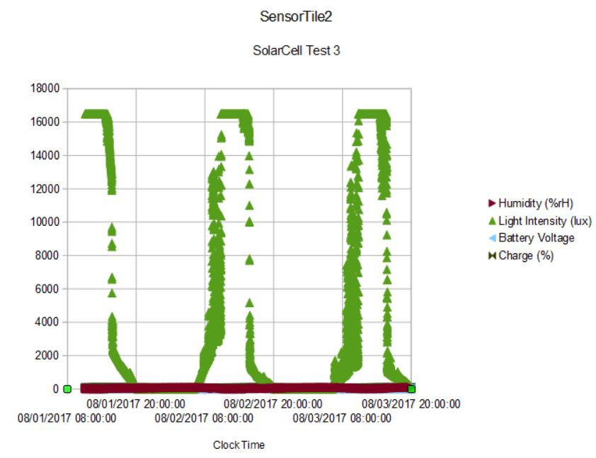
I did orient the SensorTile2 more in line with the solar cell to catch the full sun and get a better measure of the incident lux. I got three days of data before the fog came back. These are the results:
![]()
You can see that the sunlight pegs the VEML6040 at 16500 lux so the actual light incident on the solar cell for most of six hours a day is greater than this. We can estimate how much greater in a second.
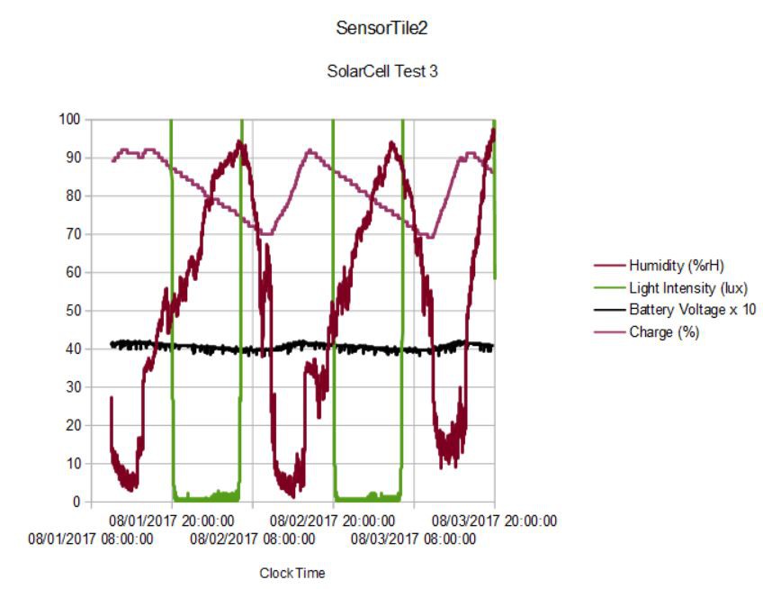
Zooming in:
![]()
you can see that when the SensorTile2 is directly exposed to full sunlight, the humidity drops like a rock (the temperature soars too). This because these MEMS pressure/humidity/temperature sensors are notoriously sensitive to incident light, which is why most people cover them with porous foam when accurate ambient measurements are the goal. In this case, I sacrificed humidity and temperature accuracy during the day anyway to get a better measure of the incident sunlight. Can't have everything on a 0.67 sq. in. pcb!
After the direct light is removed the humidity (and temperature) return to accuracy and I had to end the experiment on the third evening as the fog rolled in and the humidity climbed toward 100%.
The most interesting thing about this slightly extended experiment is that the charge state drops to 70+/- 1 and rises to 90 +/- 1 for three days. I don't see much if any dimunition in peak charge and it looks like the SensorTile2 would just keep going indefinitely under these conditions. The next revision will have an 8 MByte SPI flash so I will be able to measure for three weeks instead of three days to confirm this.
If the SensorTile2 is at steady state, then the ~1.8 mA x 24 hours ~43 mAH of required power must be provided by ~43mAH/6 hours ~ 7.2 mA of average current from the solar cell. At 17 mA per 50,000 lux (per the data sheet) this must mean the sunlight peak is closer to (7.2/17) x 50,000 ~ 21k lux, which is quite plausible.
It is gratifying to be at or near steady state with this little 50 x 33 mm solar cell. This means my goal of a perpetual environmental sensor in a compact package is close at hand. I just need to find a way to protect it from the fog!
-
Using a solar cell charger ...Part 2
08/11/2017 at 17:46 • 0 comments8/11/17
First attempts to use the solar cell charger outside were not entirely successful. This time of year we have high humidity and fog in the evening and this is interferring with one or more of the sensors on the SensorTile2. In the first attempt, I placed the SensorTile2 on a pole with the solar cell facing the sun:
![]()
You can see the green "Battery OK" led of the BQ25504 charger and the SensorTile2 hanging below it. You can also see it is overcast and not too sunny. The fog rolls in after sunset and the humidity rises...it rises so much that the humidity sensor reached saturation (got wet in fact) and the SensorTile2 simply stopped working.
The second attempt was a little more successful. I placed the SensorTile2 on a black side "table" of our barbeque with the solar cell angled to face South and more or less get the full sun from ~11 AM to ~4:45 PM. I put a glass bowl over the whole shebang after sunset to try to protect it against dew formation, which sort of worked. But the air quality sensor stopped working the first evening so I ended the experiment after two days. This is the result:
![]()
I did some scaling so everything of interest would fit on the same plot. You can see that the humidity saturates after midnight; somehow almost everything kept working into the next day.
The ambient light was measured (using the highest-range setting of the VEML6040 == 40 ms integration time) to be ~15 klux at the peak. This measurement isn't really representative of what the solar cell sees since the SensorTile2 is not at the same orientation and, in fact, gets oblique sunlight for most of the ~6 hours of direct sun exposure. I might try to orient them more closely on the next experiment to get a better measure of incident light on the solar cell.
Even at 15 klux the solar cell should be producing (15/50) x 17 mA or ~5 mA, which with ~6 hours of sunlight is ~30 mAH per 24 hour cycle. Since the device is using ~1.8 mA x 24 hours = 43 mAH per day, and the 15 klux is likely an underestimate of what the solar cell sees, this arrangement is getting close to self-sustaining. In fact you can see that the charge level measured by the MAX17048 and the battery voltage measured by the voltage divider and STM32L432 ADC both return to their maxima after the second day.
I need to repeat this experiment when the weather becomes a bit drier (which will happen soon enough). I also redesigned the SensorTile2 to replace the 1 MByte SPI flash with an 8 MByte SPI flash so I will be able to record data for ~24 days at the current (0.1 Hz) rate. Looks like, if I can keep the SensorTile2 dry, I should be able to capture a lot more data with the help of the solar cell...
-
Using a solar cell charger...Part 1
08/08/2017 at 19:53 • 0 comments08/08/17
First experiment using the BQ25504 solar cell LiPo charger with SensorTile2. I used the same sketch as I had run before where I was getting 100 hours of run time on a 150 mAH battery or 1.5 mA average power usage. This time I used a half-charged 105 mAH LiPo battery I just happened to have lying around to connect to the BQ25504 charger, and connected the BQ25004 system power and ground to the SensorTile2. I placed the whole apparatus on an inside window ledge where the sun shines directly for about three hours a day. This is the setup:
![]()
Cool spider webs, eh? The LiPo battery connects to the battery port of the BQ25504 breakout. The small 50 x 33 mm solar cell generates 40 mA @ 2.2V peak for 100 mW/cm^2 incident sunlight according to the specs. This location has direct (albeit somewhat oblique) sunlight for about three hours per day. Is this going to be enough to keep the Sensor Tile going?
In a word, no. First of all, the datasheet says 17 mA at 50,000 lux typical current. I am seeing peak ~5000 lux in this location. Three hours a day of 1.7 mA power is only 5.1 mA. I am consuming 1.5 mAH for the SensorTile2 plus 280 uAH for the battery OK led on the BQ25504 (which I should disable but haven't yet). So, 24 x 1.8 mA = 43 mA total consumed in 24 hours and 5.1 mA produced. This would be an average power usage of 1.57 mA.
Here is the actual results of the experiment:
![]() In direct sunlight, the ambient light sensor is pegged at 5500 lux (the VEML6040 has a maximum range of 16500 lux for integration time of 40 ms, whereas in this experiment I am using 160 ms*) so the actual intensity could be higher, but the direct sun only lasts ~3 hours or so at this window sill location. The BQ25504 definitely works, as the slight rises in charge level indicate while the sunlight is available. The half-charged 105 mAH LiPo battery lasted 43 hours which translates into ~1.2 mA average power usage. Really ~0.9 mA when we subtract off the 280 uA for the BQ25504 battery OK led. And this is a significant improvement over the 1.5 mA average power usage I was seeing without the BQ25504. Even the ~1.2 mA with OK led is better than the 1.57 mA I estimated above, so this likely means the actual light intensity is ~30% higher than the clipped peak measured. So likely closer to 7000 lux.
In direct sunlight, the ambient light sensor is pegged at 5500 lux (the VEML6040 has a maximum range of 16500 lux for integration time of 40 ms, whereas in this experiment I am using 160 ms*) so the actual intensity could be higher, but the direct sun only lasts ~3 hours or so at this window sill location. The BQ25504 definitely works, as the slight rises in charge level indicate while the sunlight is available. The half-charged 105 mAH LiPo battery lasted 43 hours which translates into ~1.2 mA average power usage. Really ~0.9 mA when we subtract off the 280 uA for the BQ25504 battery OK led. And this is a significant improvement over the 1.5 mA average power usage I was seeing without the BQ25504. Even the ~1.2 mA with OK led is better than the 1.57 mA I estimated above, so this likely means the actual light intensity is ~30% higher than the clipped peak measured. So likely closer to 7000 lux.Could this scheme ever perpetually run the SensorTile2? Using a larger area solar cell, sure. But if I change location and position of this little solar cell, I would need to get 18,000 lux for six hours a day to produce ~37 mA per day and if I disable the BQ25504 led I would consume ~36 mA per day. So it is possible. But even if I could just double the run time from 100 to 200 hours total or so it might be worth the effort. I am running this experiment next.
* Yes, this is due to an error in the sketch where the sensitivity was being calculated as Gsensitivty/(integrationTime + 1) instead of Gsensitivity/(1 << integrationTime). So Gsensitivity was being divided by 3 and not the correct 4 at integration time of 160 ms.
STM32L4 Sensor Tile
Small, connected device for smelling and hearing in any environment.

 In direct sunlight, the ambient light sensor is pegged at 5500 lux (the VEML6040 has a maximum range of 16500 lux for integration time of 40 ms, whereas in this experiment I am using 160 ms*) so the actual intensity could be higher, but the direct sun only lasts ~3 hours or so at this window sill location. The BQ25504 definitely works, as the slight rises in charge level indicate while the sunlight is available. The half-charged 105 mAH LiPo battery lasted 43 hours which translates into ~1.2 mA average power usage. Really ~0.9 mA when we subtract off the 280 uA for the BQ25504 battery OK led. And this is a significant improvement over the 1.5 mA average power usage I was seeing without the BQ25504. Even the ~1.2 mA with OK led is better than the 1.57 mA I estimated above, so this likely means the actual light intensity is ~30% higher than the clipped peak measured. So likely closer to 7000 lux.