Close
0%
0%

Measuring-Node-for-Equilibrium-Evaluation

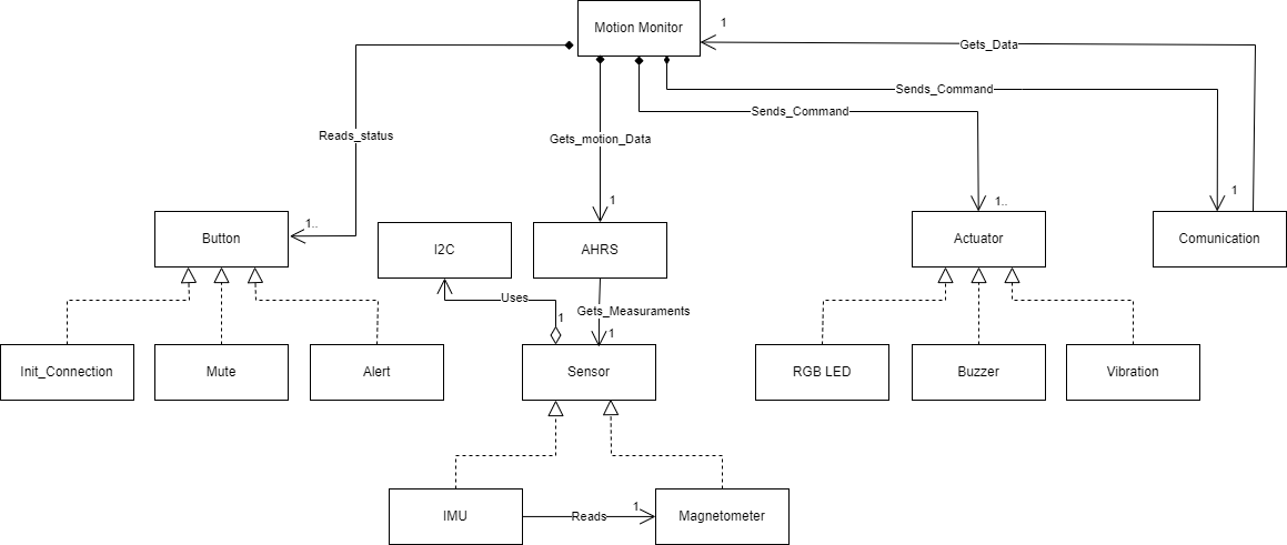
Developed a stand-alone node for equilibrium evaluation, integrating sensors and software to enhance therapy for children.

Similar projects worth following
The project focuses on developing a stand-alone measuring node for equilibrium evaluation, primarily designed to enhance therapy sessions for children with physical or developmental challenges. This innovative device integrates advanced sensor technology and interactive software applications to make therapy more engaging, interactive, and efficient.

Key Components and Technology:
Sensors: Utilizes the BMI270 and BMI150 sensors for measuring acceleration, angular speed, and magnetic fields. These sensors provide high-precision data essential for detailed motion analysis.
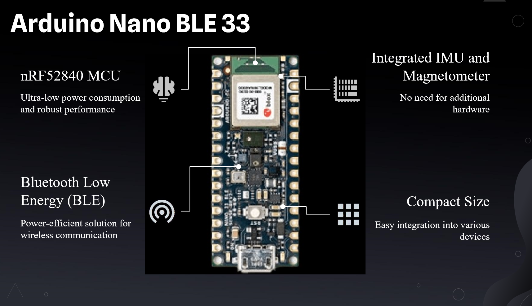
Microcontroller: Employs the Arduino Nano BLE 33 Rev2, known for its low power consumption and built-in Bluetooth Low Energy (BLE) for data transmission.
Vision System: Includes a vision system to measure patient movements and compare them with data from the accelerometers, enhancing accuracy in monitoring.
Software: Developed a Windows application in C# for therapists.

Table of Contents:

Subsystem

  • Inspiration
    • Problem Definition.
    •  Challenges in Traditional Therapy.
    • Need for an Innovative Solution.
    • The Proposed Solution.

Working Principle:

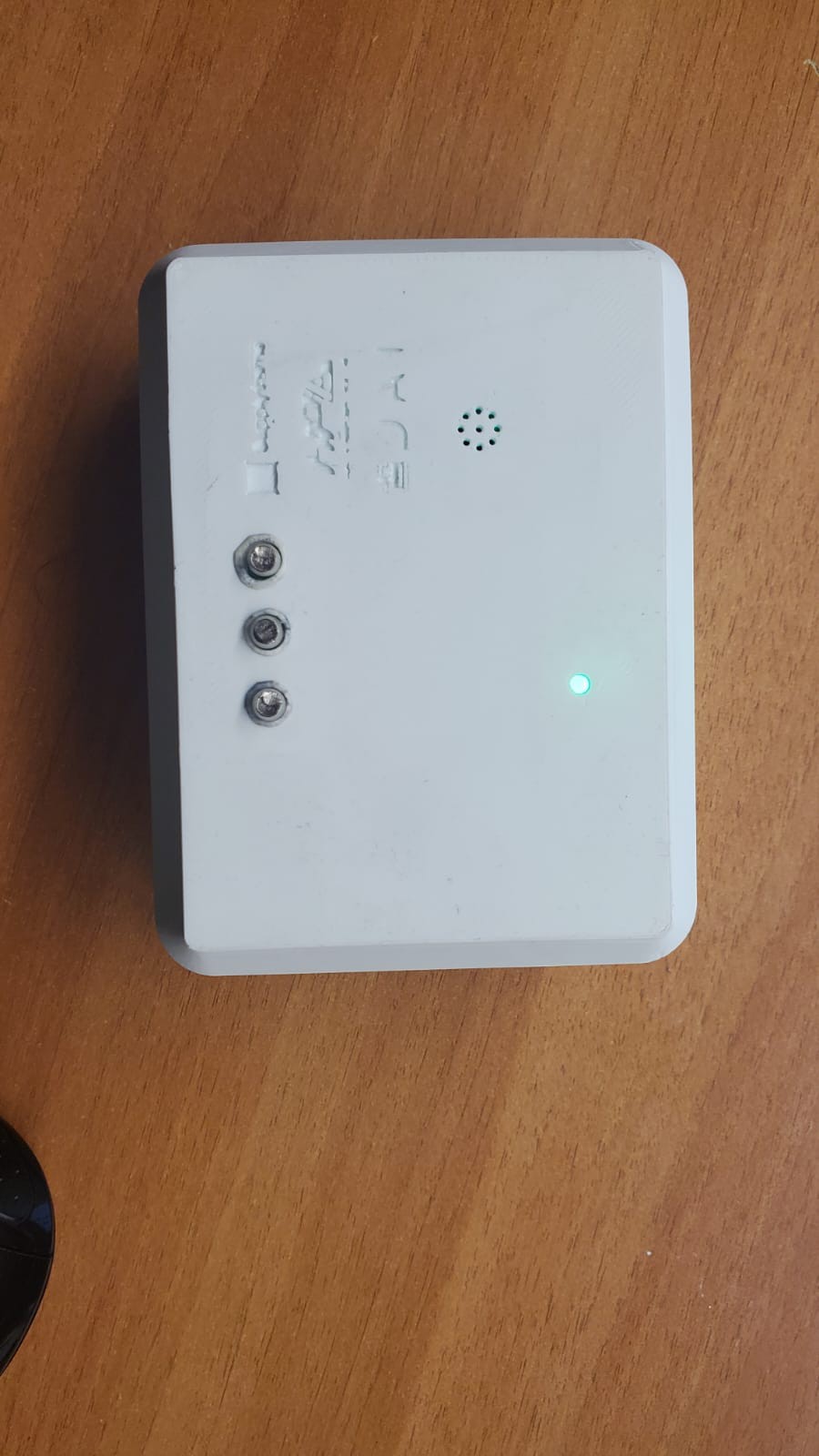
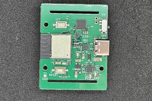
Fig. 1: Equilibrium Evaluation Node

This stand-alone equilibrium evaluation node uses mems IMU sensor  to monitor and analyze patient movements during therapy sessions. The core functionality is based on the precise measurement of acceleration, angular velocity, and magnetic fields, provided by integrated sensors.
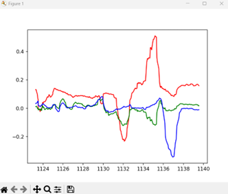
Fig. 2: Sensor Data Fusion and Analysis

The key working principle involves the fusion of data from the BMI270 and BMI150 sensors using the Madgwick filter, which improves orientation estimation. This data, combined with visual motion tracking, provides a comprehensive assessment of the patient's equilibrium.
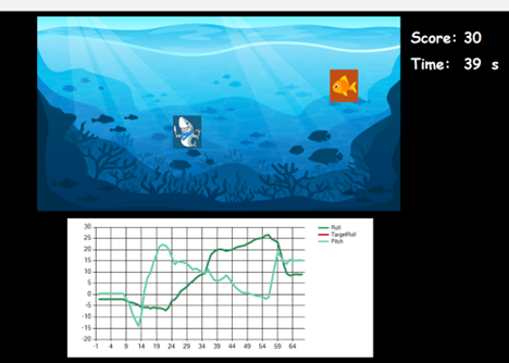
Fig. 3: Real-Time Feedback Mechanism

Once motion data is collected, the system provides real-time feedback to therapists via a user-friendly Windows application. This enables immediate adjustments to therapy exercises, enhancing their effectiveness and ensuring patient safety.

Construction:
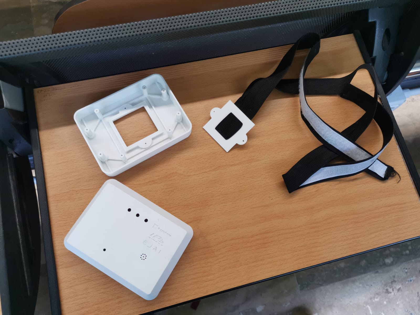
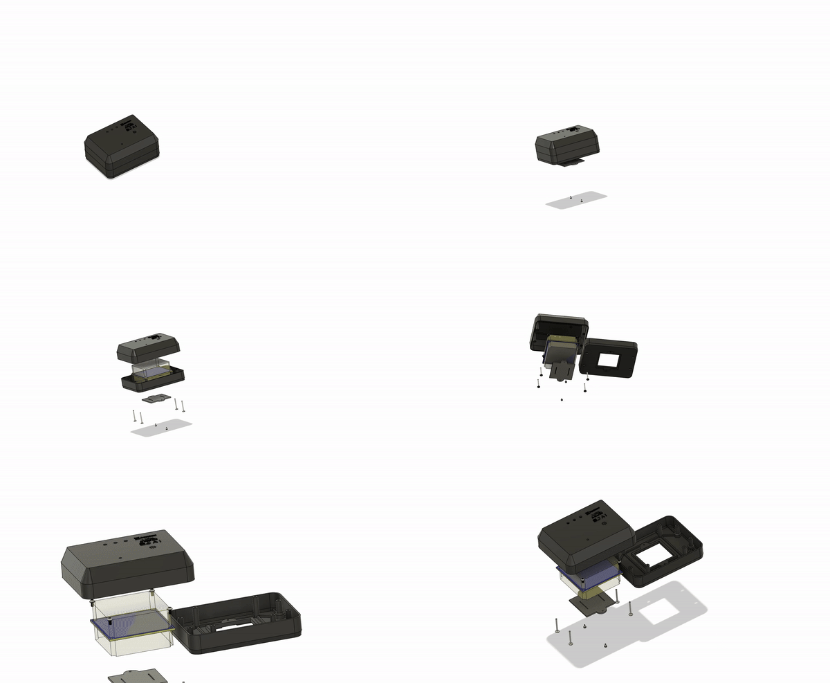
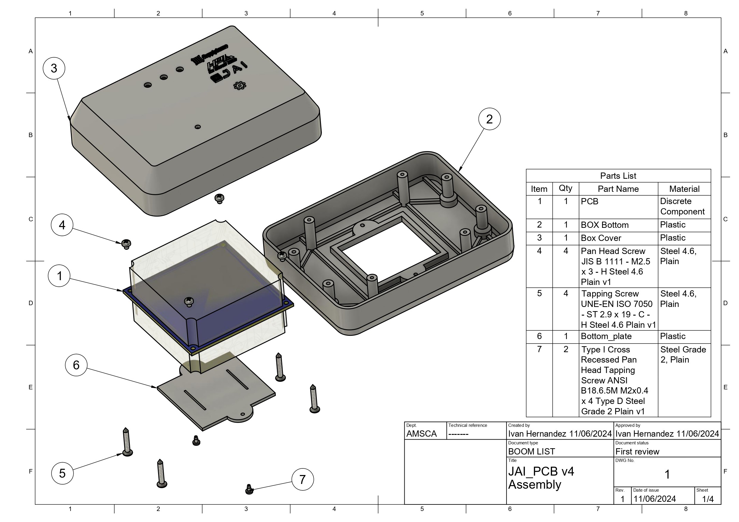
Fig. 4: Prototype Construction

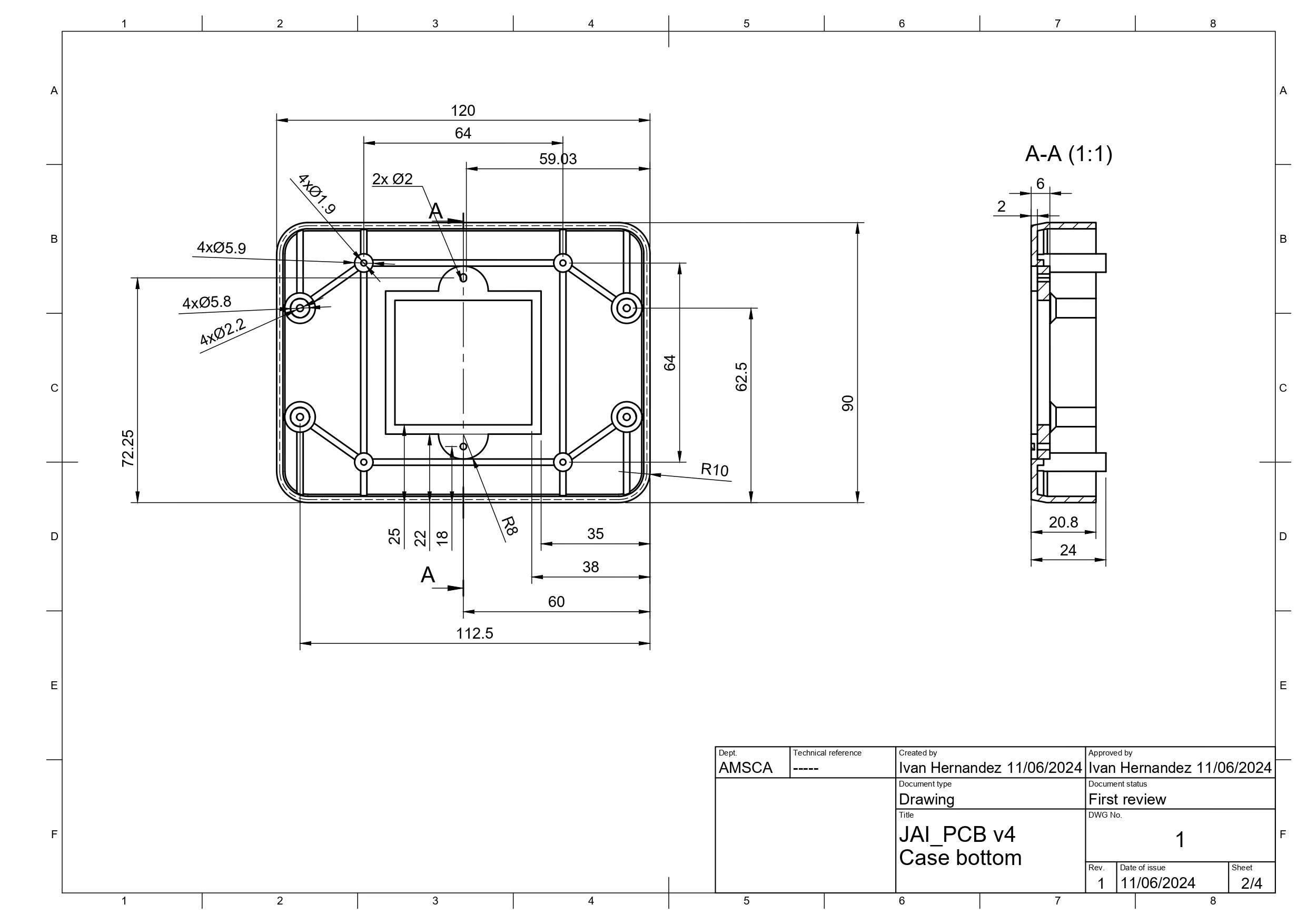
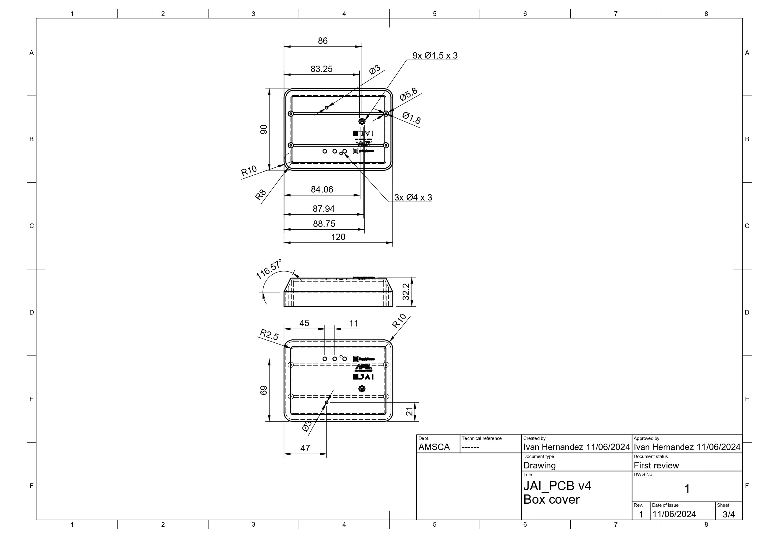
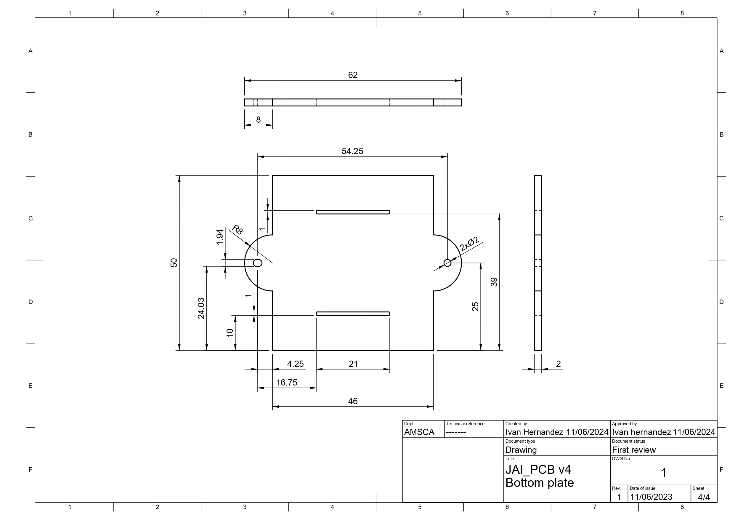
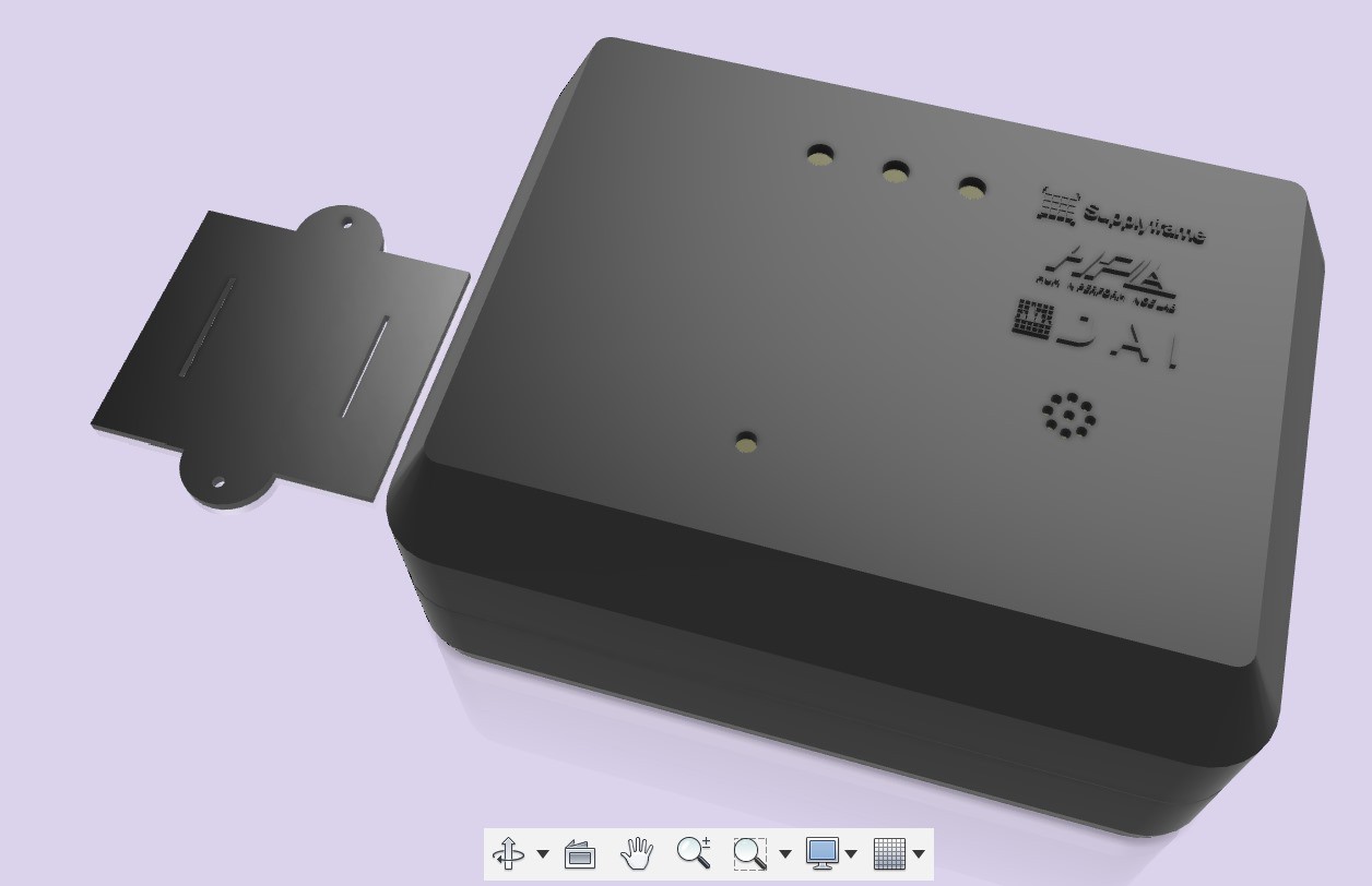
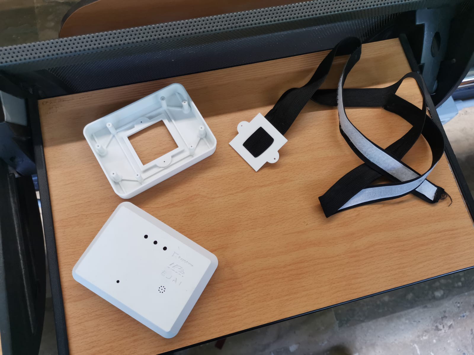
Prototyping involves 3D printing for case. FDM 3D printer technology is used.
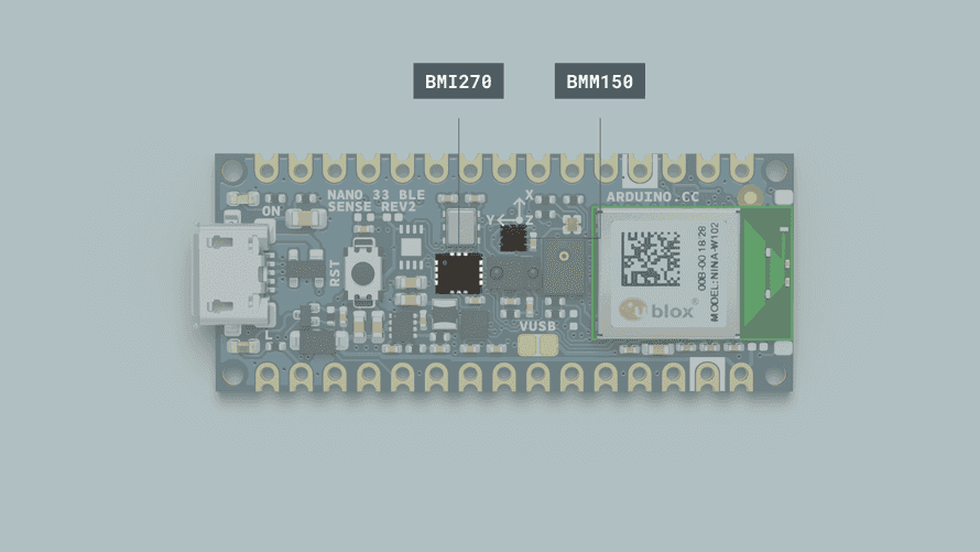
Fig. 5: Sensor Integration

The sensors (BMI270 and BMI150) are integrated into the Arduino Board, designed for compact and efficient placement. The Arduino Nano BLE 33 Rev2 microcontroller manages data processing and wireless transmission.
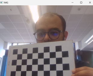
Fig. 6: Vision System Setup

A calibrated camera system tracks markers on the patient, providing an independent measurement of movements. This system is synchronized with sensor data to validate accuracy.

Conclusion

The developed equilibrium evaluation node successfully integrates high-precision sensors, an advanced vision system, and real-time data processing to enhance therapy sessions for children. The system provides accurate and reliable measurements, facilitating effective therapy and real-time adjustments.

Recommendations

  1. Expand Sensor Array: Consider adding more sensors (e.g., force sensors) for additional data points.
  2. Enhance Data Processing: Implement machine learning algorithms for advanced motion analysis.
  3. Optimize Power Consumption: Further reduce power usage to extend battery life.
  4. Increase User Training: Provide comprehensive training materials for therapists.
  5. Validate in Diverse Settings: Conduct extensive field testing to ensure reliability across various environments.
  6. Cost Reduction Strategies: Explore bulk purchasing and alternative materials to lower production costs.

Node_code.zip

x-zip-compressed - 11.57 MB - 06/13/2024 at 01:07

Download

CASE.f3z

f3z - 4.71 MB - 06/13/2024 at 01:05

Download

body1.stl

bottom case stl

Standard Tesselated Geometry - 557.89 kB - 06/12/2024 at 21:48

Download

body2.stl

cover case stl

Standard Tesselated Geometry - 261.41 kB - 06/12/2024 at 21:48

Download

Body3.stl

bottom plate stl

Standard Tesselated Geometry - 37.78 kB - 06/12/2024 at 21:48

Download

View all 8 files

  • 1 × 3D printed Case
  • 1 × Arduino BLE33 rev2 / BLE33 SENSE rev2
  • 3 × push buttons 6*6*8.5
  • 1 × push switch
  • 1 × RGB Led (MHS110RGBCT)

View all 17 components

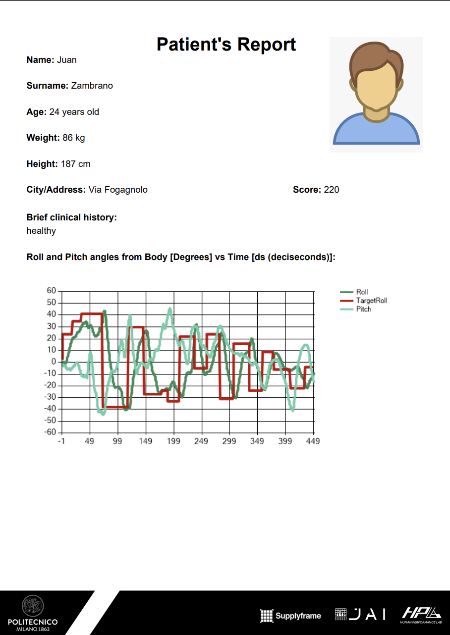
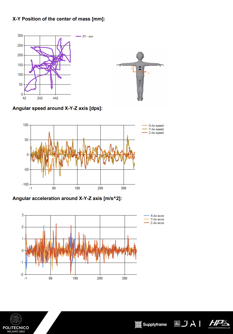
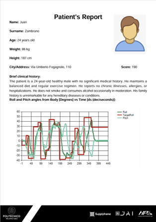
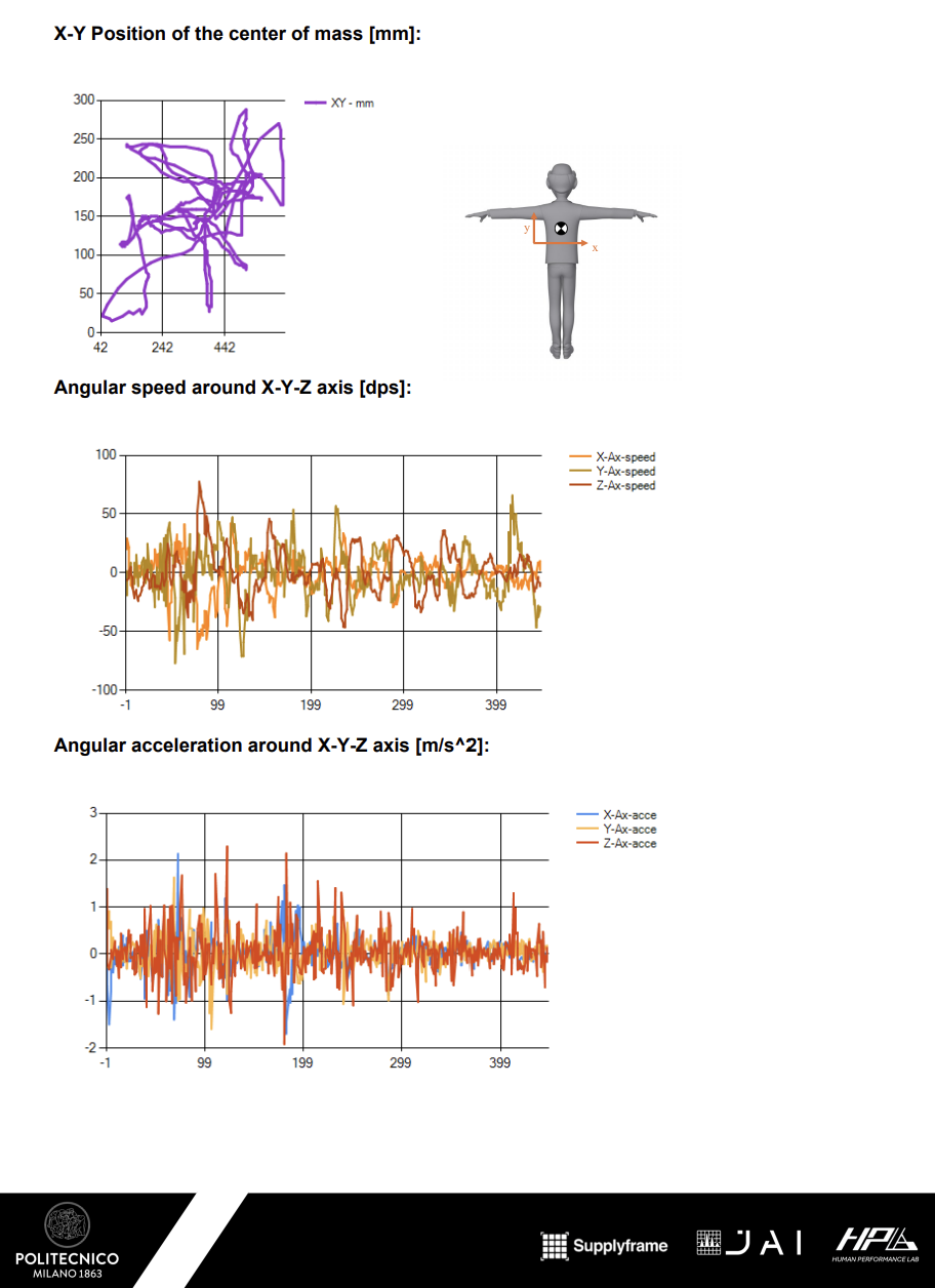
  • PATIENT REPORT SAMPLE

    Juan Diego Zambrano06/14/2024 at 19:50 0 comments

  • Software Source Files

    Ivan Hernandez06/12/2024 at 21:42 0 comments

    Node surce Code: GitHub repo

    Vision System Code: GitHub repo

    Windows APP Code: GitHub repo

  • Technical Documents

    Ivan Hernandez06/12/2024 at 21:41 0 comments


  • Software Development

    Ivan Hernandez06/12/2024 at 21:40 0 comments

    Phase 1: Requirements Gathering and Initial Planning

    At the very start of the project, we gathered around therapists,  alike and also we read some papers, ready to embark on this exciting journey. We discussed what this software needed to achieve. Therapists shared their daily challenges and ideas for a tool that could revolutionize therapy sessions. We took notes, outlining key functionalities like real-time data visualization, session logging, progress tracking, and report generation.

    Phase 2: Prototype Development

    With the requirements in hand, our team dove into setting up the development environment. We sketched out initial UI mockups, imagining how therapists would interact with the software. 

    Phase 3: Sensor Data Integration

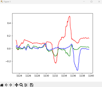
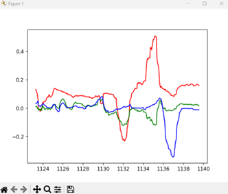
     we integrated the BMI270 and BMI150 sensors with the Arduino Nano BLE 33 Rev2. We crafted a seamless BLE communication protocol, ensuring smooth data transmission from sensors to our application. As data streamed in real-time, graphs depicting acceleration and angular velocity was plotted.

    Phase 4: User Interface Refinement

    User feedback from therapists guided the refinement of the user interface, focusing on usability and intuitive navigation. Data visualization elements were enhanced to provide clear and insightful representations of therapy session data. The refined UI was designed to be user-friendly, ensuring that therapists could easily navigate and utilize the software to its full potential.

    Phase 5: Data Storage and Reporting

    This phase focused on implementing data storage and developing report generation features. These features allowed therapists to create detailed session summaries and track patient progress. 

  • Vision System Development & Testing

    Ivan Hernandez06/12/2024 at 21:40 0 comments

    Phase 1: Requirements Analysis and Initial Planning

    The vision system development began with a comprehensive analysis of the project requirements. These requirements included high-precision tracking of patient movements and real-time feedback capabilities. An initial project plan was drafted, outlining the major milestones and timelines for the vision system development.

    Phase 2: Camera Selection and Calibration

    The next step involved selecting suitable cameras for the vision system. We opted for the laptop camera because wase the only one we have avalible. Key considerations included frame rate, field of view, and compatibility with our software. The camera underwent a thorough calibration process to ensure accurate measurement and alignment. Calibration involved using a series of known reference points to adjust the camera settings for precise tracking and measurement.

    Camera Calibration Definition
    Camera Calibration refers to the process of getting the internal and external parameters of a camera, where the internal parameters are:
    • fx and fy, the focal length multiplied by the pixel density in the x and y axes, mx and my, respectively
    • Ox and Oy, the image center points
    And the external parameters are:
    • Rotation matrix R, defining the orientation of the camera in the world frame
    • Translation matrix T, defining the position of the camera in the world frame
    If we have the camera parameters, then we can establish a transformation from 3D world coordinates to 2D image coordinates, and vice versa.

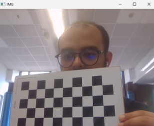
    To calibrate the camera, we need to do so using an object of known dimensions; for instance, a known calibration pattern such as a chessboard

    Then the steps are as follows:

    • Take multiple images of the chessboard from different angles and positions. The pattern should be flat.
    • Detect the corners or dots in the calibration pattern in each image. For a chessboard, this involves finding the intersection points of the black and white squares.
    • Using the known geometry of the calibration pattern and the detected key points, an initial estimate of the intrinsic parameters can be made using the Direct Linear Transformation method (DLT).
    • For each calibration image, compute the extrinsic parameters (R and T) that relate the 3D coordinates of the calibration pattern to the 2D image coordinates.
    • Estimate the nonlinear distortion effects, such as the radial and tangential distortion coefficients, for better calibration accuracy.

    Phase 3: Marker Tracking System Development

    After calibrating the web camera, i.e. getting the internal and external parameters, we can now design an application that estimates the orientation of the chessboard in a live video stream and plot the readings in real-time.

    The program is divided into two parallel threads using the threading library in python, the first thread is used to capture the live video stream using opencv library

    After that, the camera parameters are passed to the cv2.solvePnP method to get the coordinates of the board, basically the PnP method determines the coordinates of the board using the 3D coordinates of n points on the chessboard, then from the coordinates of the board we get the orientation

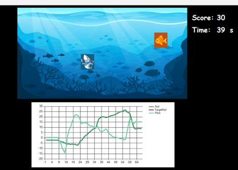
    On the other thread, a function that plots the 3 angles of the orientation (roll, pitch, yaw) in real time is implemented.

    Phase 4: Real-Time Processing and Feedback Mechanism

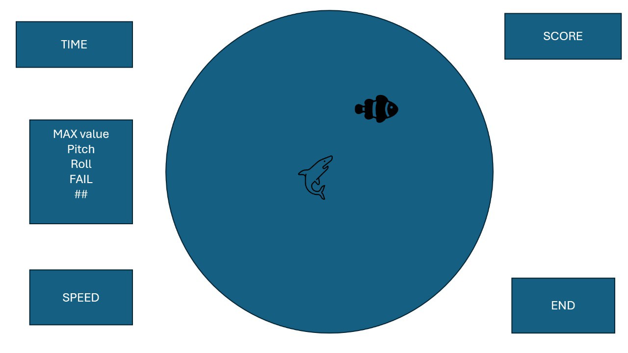
    Real-time data processing capabilities were developed to ensure immediate feedback during therapy sessions. The vision system software was optimized to process data in real-time. A feedback mechanism was implemented. This phase also involved fine-tuning the algorithms to minimize latency and ensure smooth operation in to the game.

  • Electronics/Firmware Development & Testing

    Ivan Hernandez06/12/2024 at 21:40 0 comments

    Phase 1: Electronics Selection

    The initial phase was crucial for setting the foundation of the IMU balance node. Our primary goal was to select the most suitable electronic components that would ensure precision, reliability, and seamless integration into our system. 

    •  IMU Selection: We selected the BMI270 and BMI150 IMUs for their advanced features and proven reliability. The BMI270, with its high-performance accelerometer and gyroscope, provided excellent motion sensing capabilities. The BMI150 was chosen for its compact size and efficient power consumption. Together, these sensors offered a balanced solution for accurate motion tracking and low power usage, which were essential for our application. 

    •  Microcontroller Selection: The Arduino Nano BLE 33 Rev2 was chosen as the central microcontroller for the IMU balance node. This board was selected for several key reasons: 
      • Bluetooth Low Energy (BLE) Connectivity: The integrated BLE module facilitated seamless wireless communication between the sensors and the main application, essential for real-time data transmission.
      •  Processing Power: The 32-bit ARM Cortex-M4 processor provided ample processing power to handle real-time data acquisition and processing tasks. 
      • Compact Form Factor: The small size of the Arduino Nano BLE 33 Rev2 allowed for easy integration into the overall system design without compromising on performance.

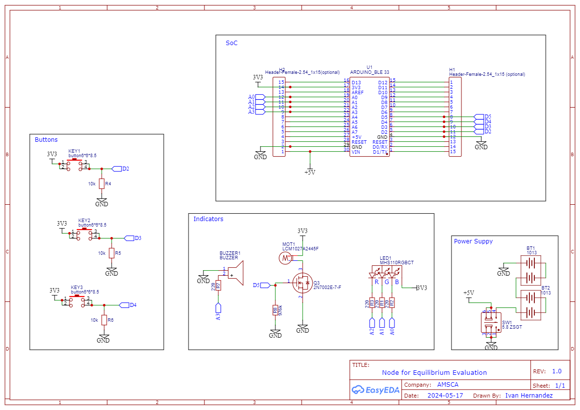
    •  Additional Electronics: To support the IMUs and the microcontroller, we incorporated various supporting electronic components: 
      •  Power Management: Efficient power regulation circuits were designed to ensure stable power supply to all components, including voltage regulators and capacitors for noise reduction. 
      • Connection Interfaces: Headers and connectors were carefully selected to facilitate easy assembly and reliable connections between the sensors, microcontroller, and other peripherals. 
      • Push buttons. 
      • RGB Led. 
      • Buzzer. 
      • Vibration Motor. 

    Phase 2: Initial Circuit Design and Prototyping

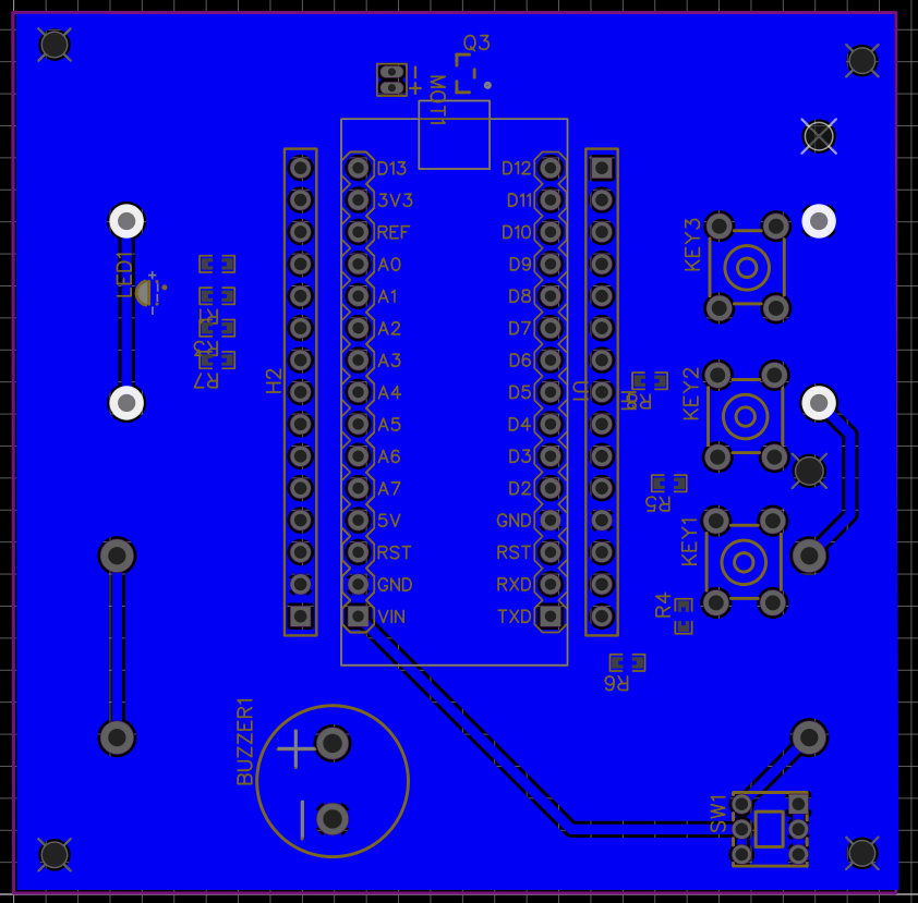
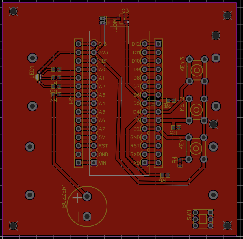
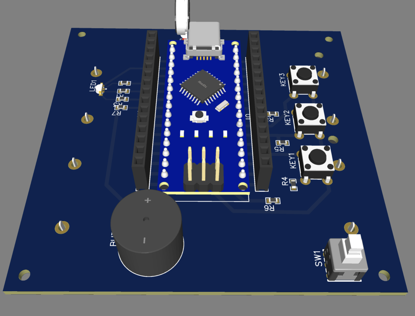
    The initial phase focused on designing the circuit for the IMU balance node. We began by selecting appropriate IMUs, settling on the BMI270 and BMI150 for their precision and reliability. Using tools like EasyEda Designer, we drafted the initial schematic and created prototype PCBs. These prototypes were essential in understanding the basic requirements and limitations of our design, ensuring a solid electronic foundation for further development.

    Phase 3: Sensor Integration and Communication Protocol

    In this phase, we integrated the BMI270 and BMI150 sensors with the Arduino Nano BLE 33 Rev2. Developing a robust communication protocol was critical, so we implemented a BLE (Bluetooth Low Energy) protocol to facilitate seamless data transmission between the sensors and the main application. This involved writing and testing code to ensure reliable data acquisition and transmission, laying the groundwork for real-time monitoring.

    ----------more ----------

    Phase 4: Firmware Development and Calibration

    Firmware development was undertaken to process and manage the sensor data. Using the Arduino IDE, we wrote firmware to capture and filter raw data from the IMUs. We implemented the Madgwick filter for sensor fusion, which significantly improved orientation estimation. Calibration routines were developed to ensure accuracy, involving extensive testing to fine-tune the sensor readings and eliminate drift.

    Phase 5: System Integration and Testing

    The IMU balance node was integrated with the overall system, including the vision system. Comprehensive testing was conducted to ensure all components worked harmoniously. We focused on synchronizing data from the IMUs with the vision system, validating the accuracy and reliability of the combined data. This phase involved iterative testing and refinement, ensuring that the system met performance expectations.

    Phase 6: Optimization and Power Management...

    Read more »

  • Mechanical Development & Testing

    Ivan Hernandez06/12/2024 at 21:35 0 comments

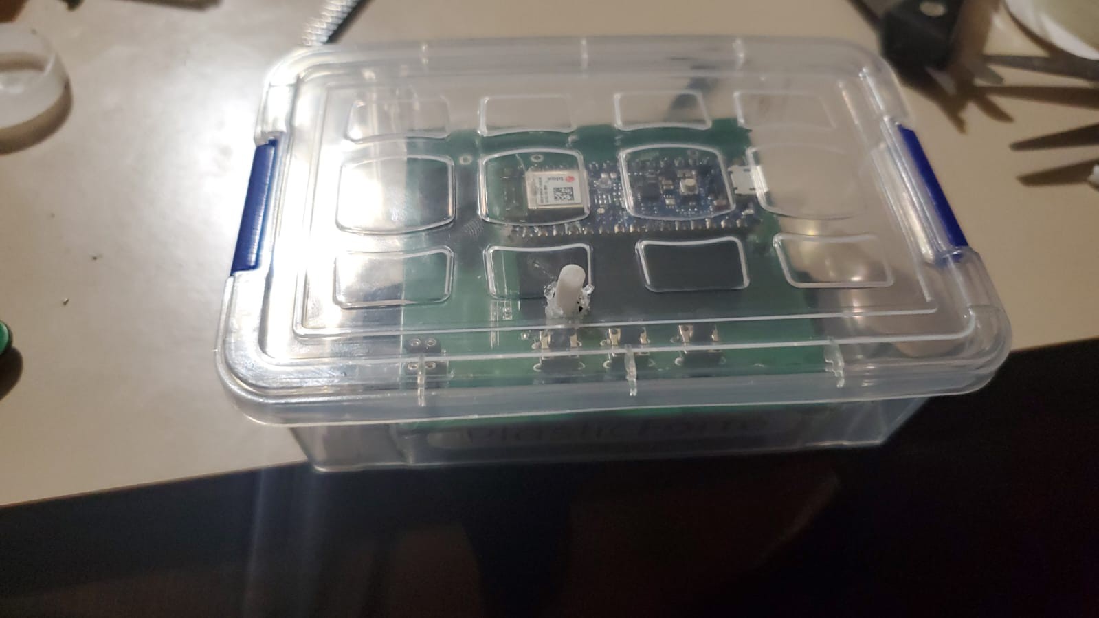
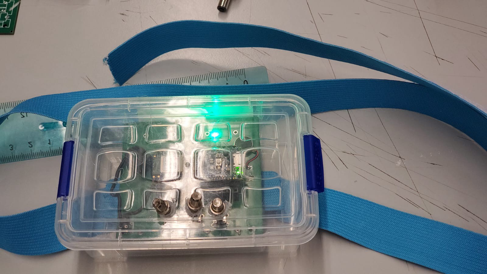
    Phase 1: Initial Prototype with Off-the-Shelf Plastic Box


    The initial mechanical prototype of the IMU balance node was housed in an off-the-shelf plastic box, readily available from various suppliers. This approach allowed us to quickly assemble the components and focus on the functionality of the electronics and firmware. The primary goal during this phase was to validate the core functionalities of the system without investing significant time and resources into custom enclosures. The plastic box provided basic protection and easy access to the internal components for debugging and adjustments.


    Phase 2: Custom Case Design for Enhanced Usability

    Having validated the system's core functionalities, we moved on to designing a custom case tailored to our specific needs. Using CAD software, we modeled a case that offered better protection, accessibility, and aesthetics. This custom design addressed several limitations of the off-the-shelf box:

    • Improved Fit: The new case was designed to snugly fit all internal components, minimizing movement and potential damage.
    • Accessibility: Ports and buttons were strategically placed to ensure easy access for users].


    This custom case was 3D printed using  PLA, allowing us to rapidly iterate on the design and make necessary adjustments based on initial testing feedback.

    Phase 3: Integration of Silicone LED Diffuser

    To enhance the user interface, we integrated a silicone diffuser for the LEDs. The diffuser served multiple purposes:

    • Improved Visibility: The silicone material diffused the LED light evenly, making it easier for users to see the indicators under various lighting conditions.
    • Aesthetic Appeal: The diffuser gave the device a sleek, professional look, aligning with our goal of creating a user-friendly and visually appealing product.
    • Protection: The silicone also added an extra layer of protection for the LEDs, shielding them from dust and impacts.

    The design was optimized to ensure that the silicone diffuser could be easily installed and replaced if necessary, without compromising the overall integrity of the case.

    Phase 4: Extension Design for Push Buttons

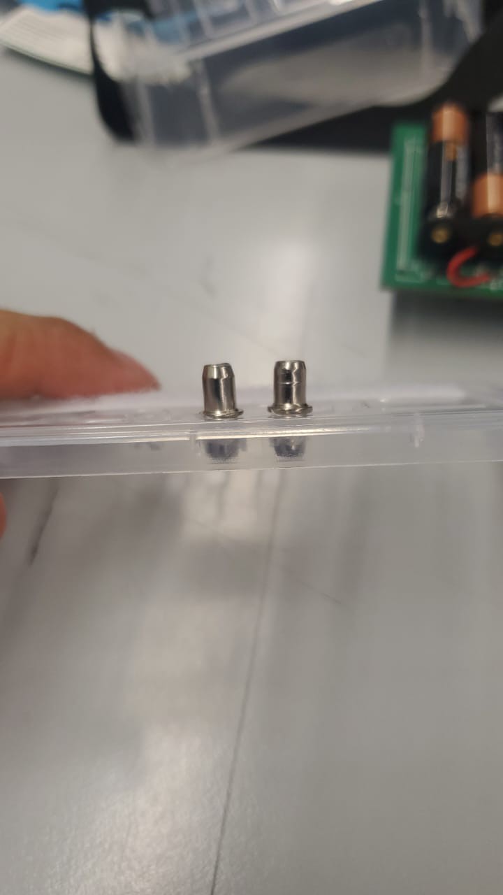
    Another key improvement in our custom case design was the addition of extensions for the push buttons. These extensions allowed the buttons to be accessible from outside the case, enhancing the usability of the device. The extensions were designed with the following considerations:

    • Tactile Feedback: Ensuring that the extensions provided clear and responsive feedback to the user, maintaining the functionality of the original buttons.
    • Durability: The extensions were made from robust materials to withstand frequent use and potential rough handling.
    • Ease of Assembly: The design allowed for straightforward installation, ensuring that the extensions aligned perfectly with the internal push buttons.

  • Inspiration

    Ivan Hernandez06/12/2024 at 16:33 0 comments

    Problem Definition

    Therapy for children, particularly those with physical or developmental challenges, often requires repetitive and structured activities to improve motor skills, balance, and coordination. Traditional methods, while effective, can be monotonous and lack engagement, making it difficult for children to stay motivated and enthusiastic throughout their therapy sessions. This lack of engagement can lead to reduced effectiveness of the therapy, slower progress, and, in some cases, a complete aversion to the necessary exercises.

    1.1.                 Challenges in Traditional Therapy

    • Monotony and Lack of Engagement: Traditional therapy exercises can be repetitive and uninteresting, causing children to lose interest quickly. This disengagement can significantly hinder their progress and overall therapy outcomes.
    • Limited Interaction and Feedback: Standard therapy practices often lack interactive elements that provide real-time feedback to both the therapist and the child. This can make it difficult to adjust exercises in real-time to better suit the child's immediate needs (Ferreira, 2020).
    • Difficulty in Monitoring Progress: Monitoring a child's progress typically involves subjective assessments and manual record-keeping. This method is not only time-consuming but can also lead to inconsistencies and inaccuracies in tracking improvements.
    • Limited Motivation: Children may struggle to understand the importance of their therapy exercises and thus may not be motivated to perform them diligently. This lack of motivation can slow down their progress and reduce the overall effectiveness of the therapy (Brezinka, 2012).

    1.2.                 Need for an Innovative Solution

    Given these challenges, there is a significant need for a device that can make therapy sessions more engaging, interactive, and efficient. The ideal solution would incorporate elements that make therapy fun and motivating for children while providing therapists with accurate, real-time data on the child's performance and progress.

    1.3.                 The Proposed Solution

    The device we propose is designed specifically to address these issues by integrating advanced sensor technology with interactive software applications. This stand-alone measuring node aims to enhance therapy sessions in several keyways:

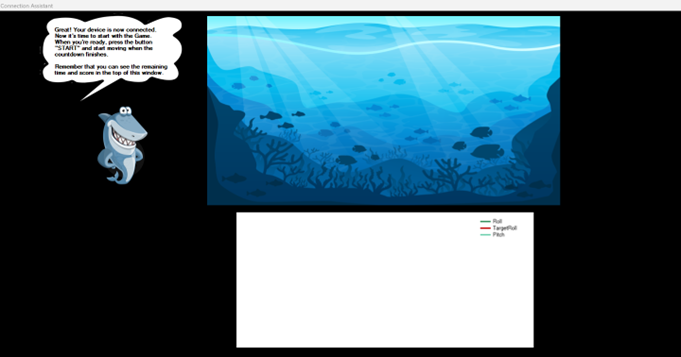
    • Interactive Therapy Sessions: By incorporating interactive elements, such as a rehabilitation game developed in Python using the Pygame library for the camera or .Net for the sensor node, the device can turn mundane exercises into engaging activities. Children can control game elements through their movements, which makes the therapy sessions more enjoyable, fun, and motivating.  (M, 2022).
    • Real-time Feedback and Monitoring: The device provides real-time feedback to both the therapist and the child. This immediate feedback allows for on-the-fly adjustments to exercises, ensuring that the therapy remains effective.
    • Accurate Progress Tracking: The device includes sensors that accurately measure the child’s movements and performance. These measurements are processed and stored and can be used to generate detailed PDF reports. These reports provide a comprehensive overview of the child’s progress, enabling more informed decisions about their therapy plan.
    • Convenience for Therapists: The Windows application developed for this device is user-friendly, allowing therapists to easily set up sessions, monitor progress, and generate reports. This ease of use reduces the administrative burden on therapists, allowing them to focus more on direct patient care.

View all 8 project logs

  • 1
    Step 1

    see the github to check the instructions of the code developed for the arduino

  • 2
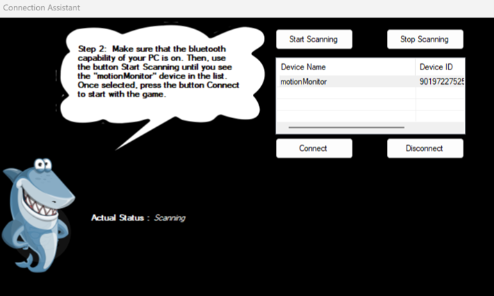
    Step 2

View all instructions

Enjoy this project?

Share

Discussions

Similar Projects

Does this project spark your interest?

Become a member to follow this project and never miss any updates