 Lithium ION
Whenever we need analog/sound out from a microcontroller or digital processing unit then DAC(Digital to Analog Converter) is used. Which works as a basic digital to analog conversion unit. Basically DAC works on exactly the opposite phenomenon of ADC (Analog to Digital Converter). As it is cleared from name, DAC - a digital signal will be given as input and the Analog signal will be the output. This digital signal is fed into the DAC input register. After filling up the whole input register, it enables the conversion based on the input value and produces an analog signal corresponding to that, it may be done serially or in parallel.
And in this conversion the timing plays a very crucial role, because every DAC has conversion and settling time. So there will be a little delay from input to output, maybe in microseconds. This article is sponsored by PCBWay, to get custom Arduino please visit this link. PCBWay provide most affordable PCB prototyping and assembly services. Get the full Quote of your custom PCB now.
PWM as DAC:
Usually in small microcontrollers the DAC feature is not available because of low cost prototyping and the signal processing is not required every time. If you don’t want to use external DAC modules then PWM function as DAC is the best low cost alternative to use. PWM can be modulated as per the signal we want to produce. PWM is nothing but a varying duty cycle constant time period wave, the duty can be controlled by sending an array of values in the Arduino PWM generator or by an external Potentiometer.
Usually in DAC the conversion is done when the input register is filled from the data but here in PWM the mapping is done by programming the Arduino to produce a particular signal. I will show two examples, to generate Sinewave by sending array of values in PWM and in second to generate a stable DC signal out of PWM using potentiometer.
Judging the quality of DAC:
There are few figures of merit I want to discuss. When talking about signal conversion from one to another form. In this way it is easy to compare the PWM as DAC and the actual DAC. There are different algorithms and architectures but we want to discuss only Resolution and conversion time.
Resolution depends on step size, shows how closely two values of signal it is able to differentiate from each other. Bit size shows the total number of steps it will take to get max output. Let's take a 10 Bit DAC for example and the total steps are calculated as 2^10-1, which are 1024 steps in total (including zero). And Resolution is given by Vref/1023, where Vref is the taken as the maximum voltage value of the signal we are measuring. If we are using a 8 bit DAC there will be 256 total steps. DAC can take 256 steps to go from zero to the max value, hence defining the resolution of DAC.
Working of PWM:
With Pulse-Width Modulation (PWM), An analogue voltage is generated by varying the proportion of the duty cycle of square wave. By decreasing the On/off time of a time period of PWM we can generate different signals and tones.
In DAC 10bit means a total of 1024 steps, but here in PWM 10bit means that the whole time period of square wave is broken into 1024 parts, which overall increases the resolution.
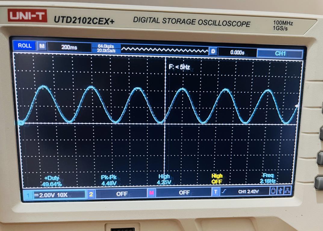
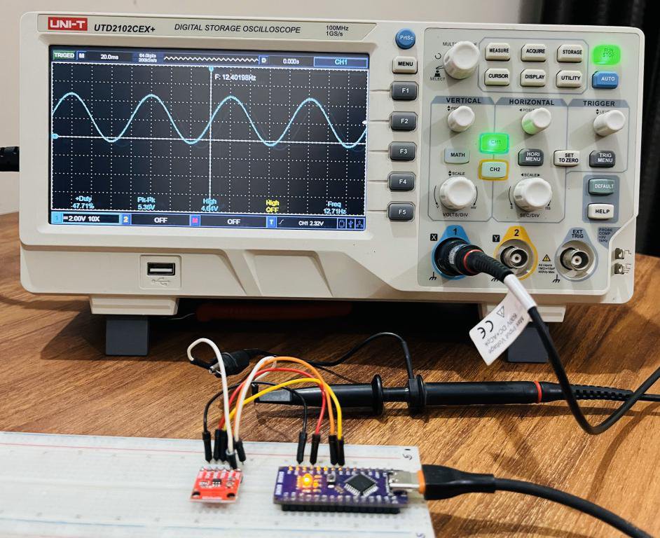
But you can see the signal is not continues, it's not a analog signal. But we need a continuous time signal out of PWM. To achieve this we can either connect a capacitor across the output, or I would recommend to add a 2nd order low pass filter to PWM output. Low pass filter or capacitor acts as an averaging circuit, takes the average of the PWM hence give a smooth analog signal in output.
Data, PWM and Sine function used here:
I want to generate a Sine wave which is known as a very fundamental analog signal. So I am using 50 samples of 10 bit data (array) and 8 bit PWM value mapping function. Also I am sharing this formula to compute the number of samples and data values of sine waves. The formula only works with...
Read more »
 agp.cooper
 Giovanni Carrera
 doctek