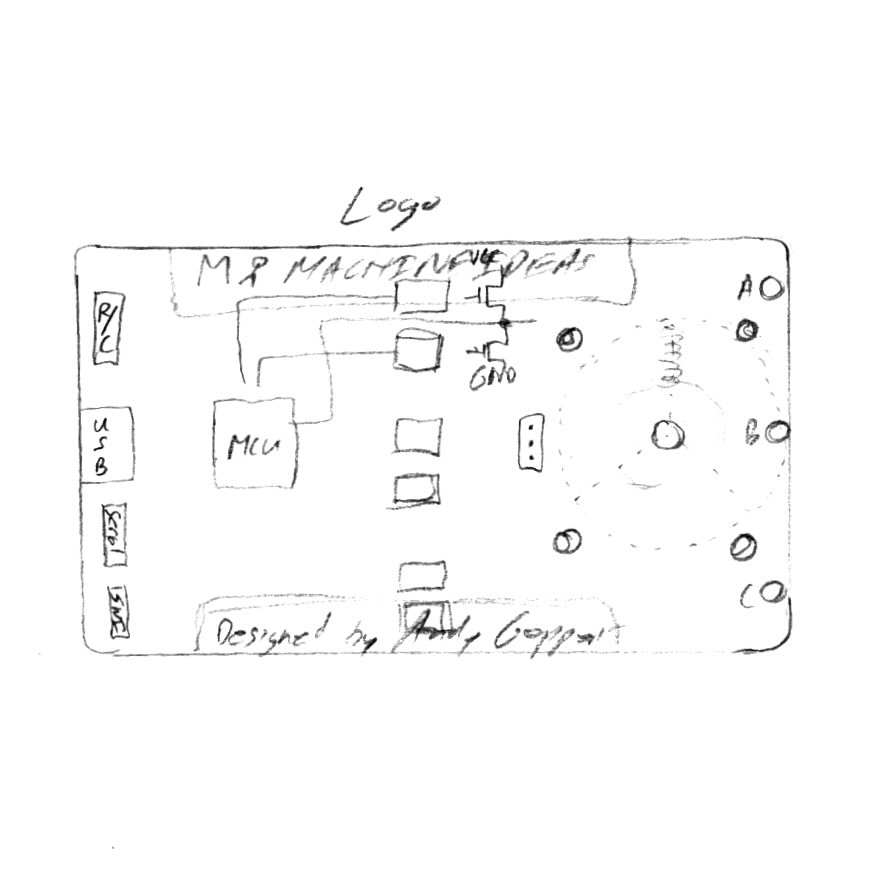
This is the first sketch I drew to capture the concept on paper:

My vision is to show the entire motor concept from the front side of the card, including the most relevant schematic elements. By having everything accessible from the front side, I can experiment and probe the different signals, along with making firmware changes, in one clean set-up.
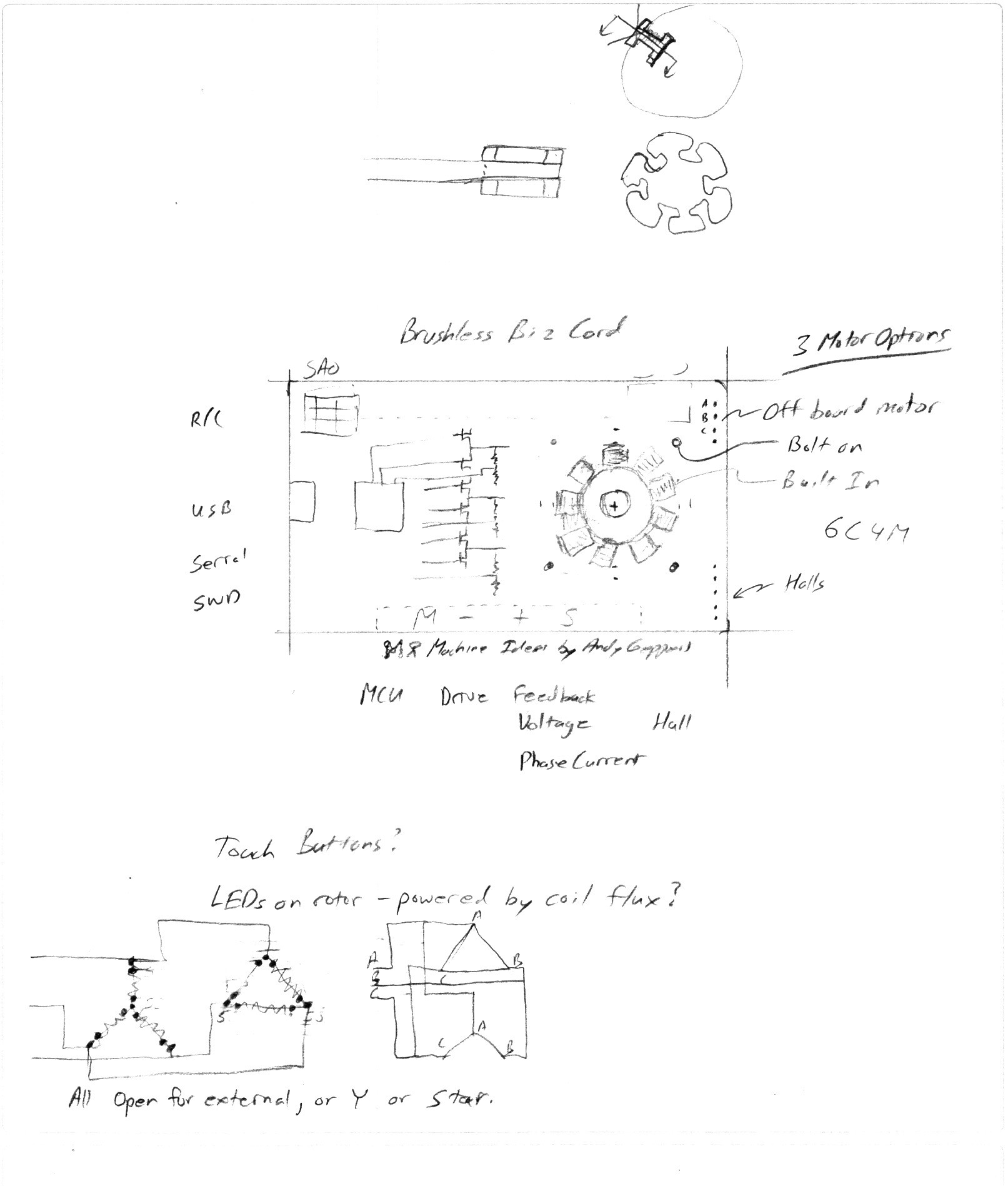
Next I started to think about the structure and placement of headers:

Making the motor have an optional WYE or DELTA winding configuration through solder jumpers will allow even more experimentation. The winding configuration has the potential to change the performance characteristics significantly, so I wanted that option to be available.
Additionally, I have found that having four buttons enables easy access to more functionality in the future, so that needs to be part of the design. Furthermore, an SAO port lends itself to expandability and makes it easy to install an SAO OLED, which I've been making and using recently.
Of course, more fun ideas start to flow. I'd like to have LEDs which indicate which coils are energized, and the polarity. Or maybe add LEDs to the rotor itself to visualize the pulses of current in the coils through inductive coupling?! These ideas will have to wait until I get the basic functionality enabled.
 Andy Geppert
Discussions
Become a Hackaday.io Member
Create an account to leave a comment. Already have an account? Log In.