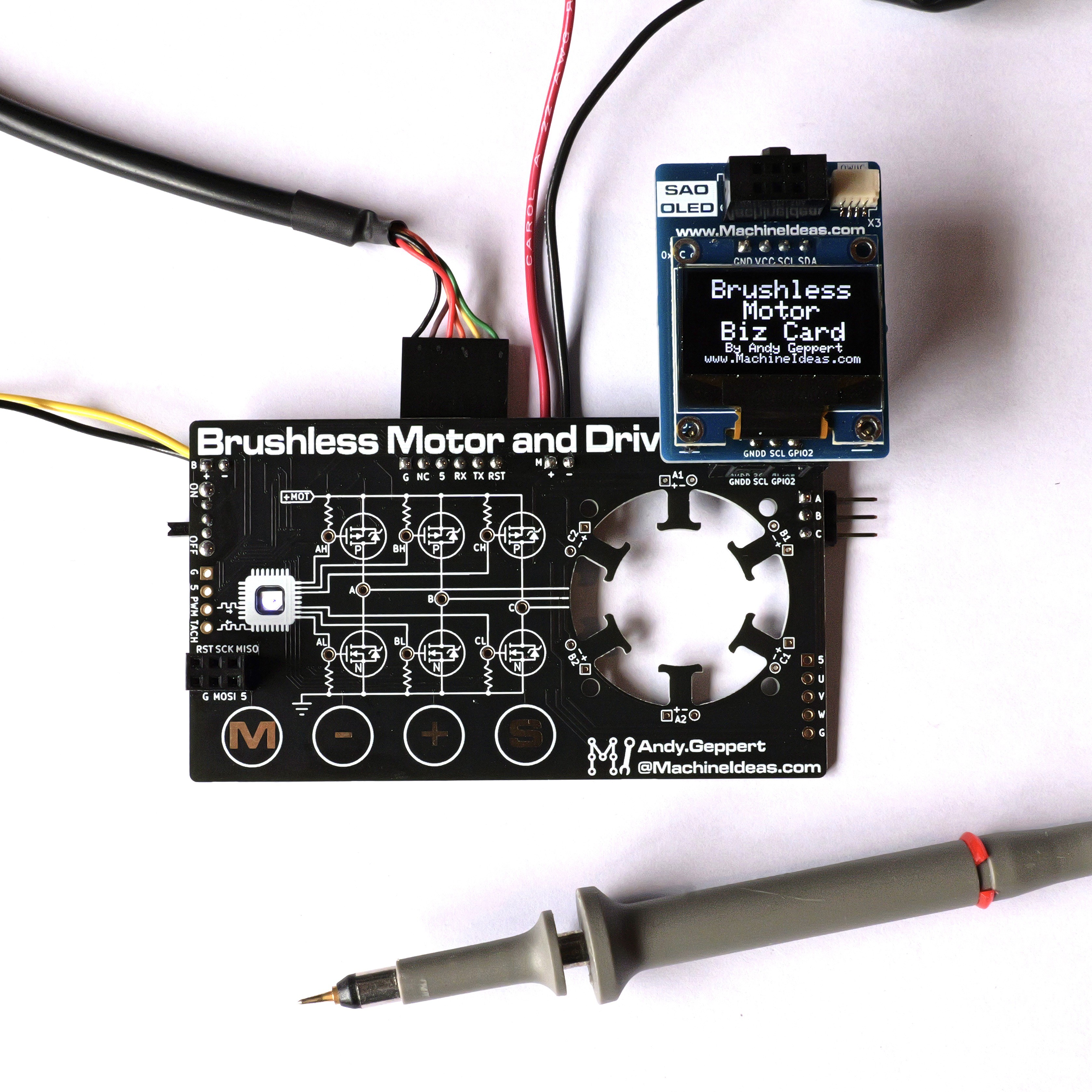
Nice to make some relatively easy progress and confirm more of the board is working:

Time to get serious about installing the 3 half bridges and bringing up the PWMs and some open loop motor control!
NOTES:
1) The cable is a USB to 5V FTDI converter, for programming. No built-in USB capability on this first prototype. I'd like to add USB-C later on.
2) The yellow and black pair of wires is to power the logic side, when the FTDI cable is not used.
3) The red and black pair of wires is to power the motor driver side, and allows me to current limit that part of the circuit during bring-up.
4) There is an open solder jumper I can use to bridge logic and motor power so only one power source is needed.
 Andy Geppert
Discussions
Become a Hackaday.io Member
Create an account to leave a comment. Already have an account? Log In.