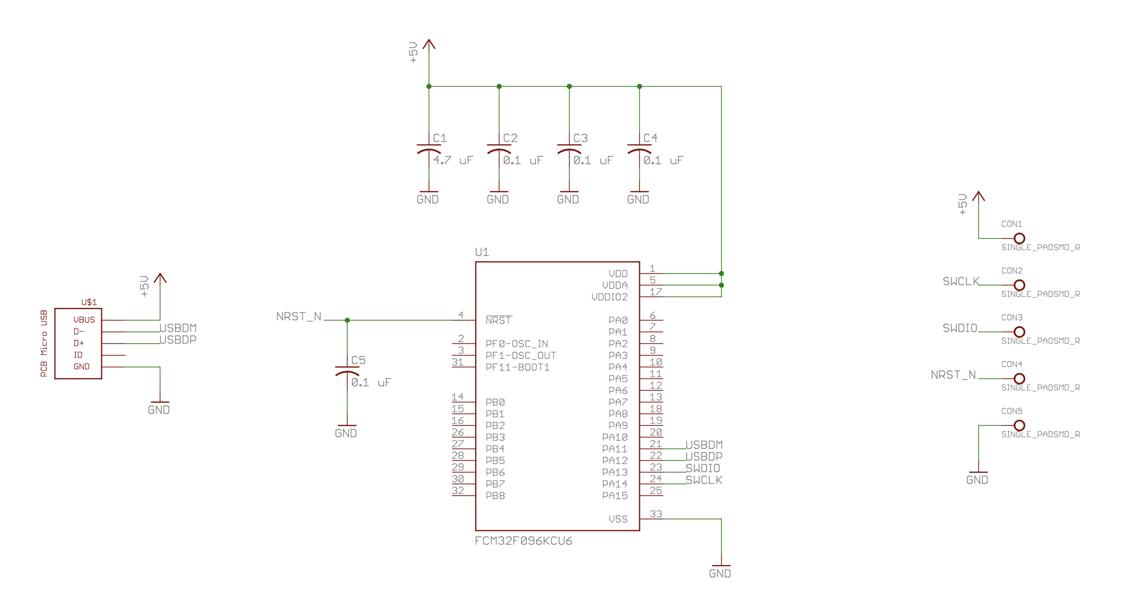
The actual circuit is very simple. The only components are the FCM32F096 and a few bypass capacitors. I put a 0.1 uF cap on every power input and the reset signal (which has an internal pull-up). A 4.7 uF bulk cap is less than the maximum 10 uF specified for USB devices to support hot-plugging. Probably it would work if some of the caps were eliminated.

The USB connector is from Juan Jesus' Eagle library. I selected the older USB MIcro-B connector instead of USB-C because it uses a thinner 0.6 mm PCB. One of the issues in his github repo suggests that using 0.8 mm is better for USB-C. Check out his work. It is very inventive and with the proper 3D printed enclosure I'm convinced one could design a USB device that needs no separate USB connector.
Five SMT pads round out the design for a quick&dirty SWD ICSP programming interface. Since the 'F096 works with either 5V or 3.3V, it can be powered by either interface.
PCB Layout of the 89x50mm card was easy. But since the circuitry takes up so little room I was left with vast expanses of PCB real-estate just begging for artwork of some kind. Sadly I'm not an artist so I decided to stick with words.
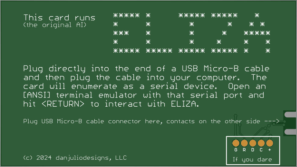
The back of the card would contain instructions.

The 5x5 pixel ELIZA tries to evoke the era of banners on line printers that might have existed at the time the program was originally written.
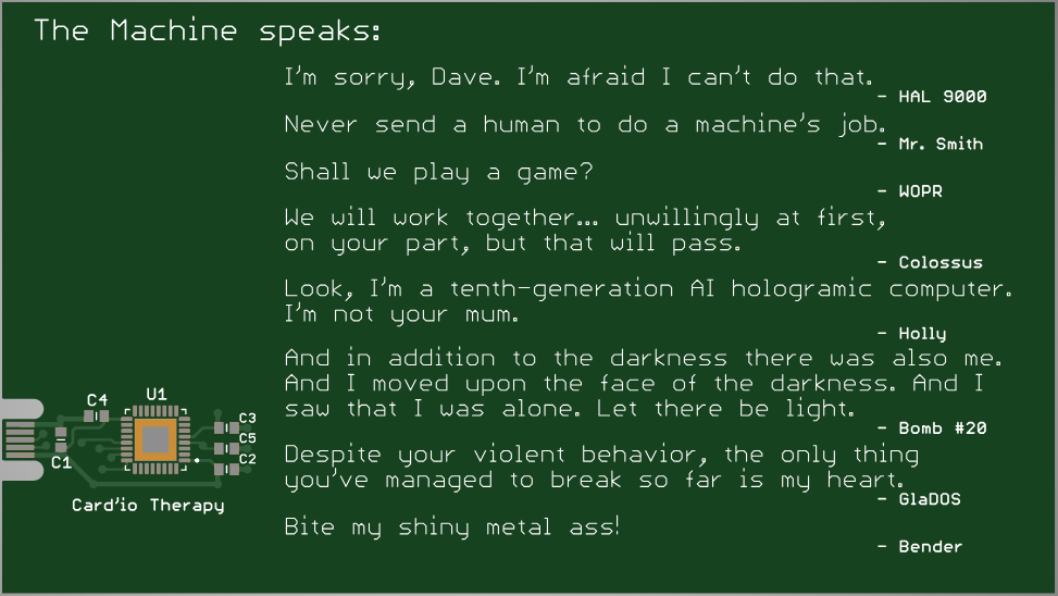
I intended the front of the card to be covered by my - or others - printed business card but I wanted to leave a little easter egg so it includes an homage to some of the naughty AIs that have graced our little and big screens over time. Do you know them all?

"Card'io Therapy" was what a friend suggested I should call this project.
The `F096 is nominally 0.8 mm thick, so along with a 0.6mm thick PCB the maximum thickness is slightly more than 1.4mm (accounting for some solder).
I waited until I had another PCB prototype to build and sent gerbers for this project along with that to PCBWay (no sponserships here, but I do like them) so I wouldn't have to burden this project with the shipping cost. I selected the basic Green + White also to minimize costs but these would also look very cool in Black + White.
Next up was to actually write some code.
 Dan Julio
Discussions
Become a Hackaday.io Member
Create an account to leave a comment. Already have an account? Log In.