 Dan Julio
Once the 'F103-based project was up and running on the dev board I ported my code to a new project based on the STM32F042K6. That went pretty smoothly but of course the final link stage would fail because the code size and RAM requirements exceed that of the part. Fortunately this information is defined in the automatically generated linker script and it was easy enough to change the Flash length to 256KB and RAM to 24KB. Now I actually had data to try to load into the hardware when the PCBs arrived. (Edit: the firmware, minus the proprietary ST USB device library is in the Files section).
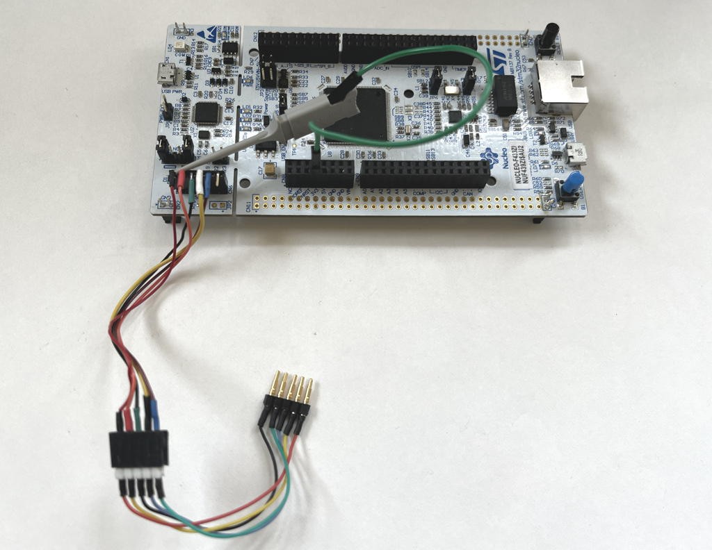
Assembling the PCB was trivial so I excitedly built up a wiring harness with a set of pogo-pins plugged into a 0.1" header that had a male header on the other side and could connect to either the ST or Flashchip dev board programmers.
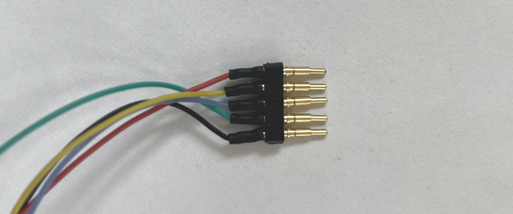
To program I just press the pogo pins against the SMT pads on an assembled PCB and manipulate the PC with my other hand. Not as elegant as some ICSP headers but it works well-enough. For volume production it would be easy to design and 3D print a programming fixture which could hold the target board and ICSP header in place.
(the clip supplies 3.3V to the card)
My first attempt at programming was a failure. I tried to use the STLink programmer from within STM32CubeIDE. The Flashchip chip ID was unrecognized and the programmer refused to even try. I'm not familiar enough with the way the programming software works under the hood to try other things, so after a little googling, I abandoned this approach.
Next up was to try the Flashchip dev board DAPlink programmer. I figured their programmer would recognized their own chip. Again, no go. Each programming attempt resulted in a FAIL file. Sometimes it just hung downloading the file to the board. Arghh. Now I was a little worried.
My previous searches revealed the existence of the STM32CubeProgammer software. Thinking it might be a little more flexible I downloaded it on the PC. Connecting to the STLink programmer actually resulted in successful communication with the 'F096 and I was psyched to press the program button. Woo-hoo, programming was successful. Quickly I plugged the board into USB and looked to see if a USB Serial port enumerated. No go. Nothing. It was dead. So back to the programming software and reading the flash back. It looked OK. The beginning matched the compiled binaries and at the end I saw all the hard-coded strings for ELIZA responses. What the ??? Then I saw the programming software could compare the read data with a file. BOOM. A entire section in the middle was incorrect. About 22KB in (of a 46KB program). No matter what I tried this always occurred. Once again my lack of knowledge of the ST world left me floundering and I was thinking that this project might be a failure.
During the various programming attempts I tried plugging and unplugging the STLink programmer. One time when a previous DAPlink file window was still on the screen (it had reverted to a top-level view when I unplugged the Flashlink dev board) I saw that the STLink programmer was also a DAPlink programmer as Windows changed the window to contain the DAPlink default files. Huh. OK, what the hell. While holding the programming header I dragged the HEX file to the window. The window went away and then came back after the programmer finished. No FAIL file. OMG. I hurriedly plugged in the USB Micro-B cable to the card. TADA - I was rewarded with a new serial port! I started the terminal emulator with that port and hit Return. ELIZA said hello back to me. I'm sure you all know that feeling of elation that comes over you after you solve some issue you've been fighting and perhaps almost given up hope of solving. Life was good. I had my business card.
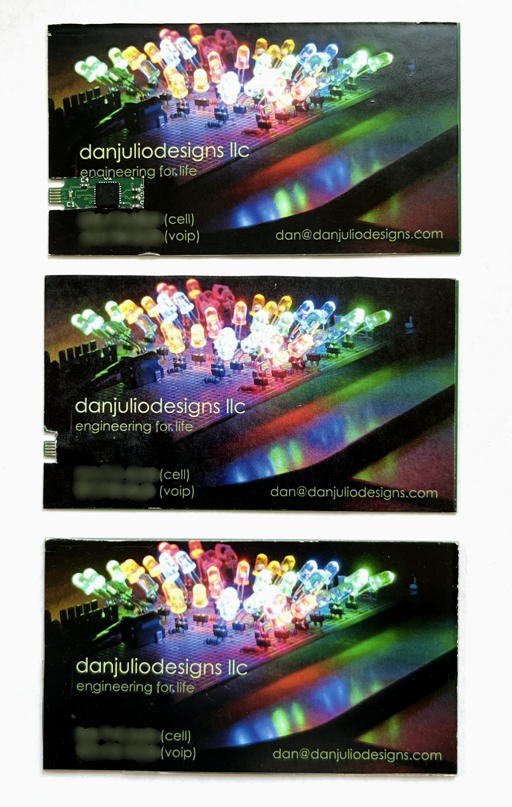
Next up was playing with how to apply the business card graphic to the base PCB. The graphics are printed on a glossy paper and I use carpet tape to adhere them (it is very thin and very sticky).
(my trimming skills need practice...)
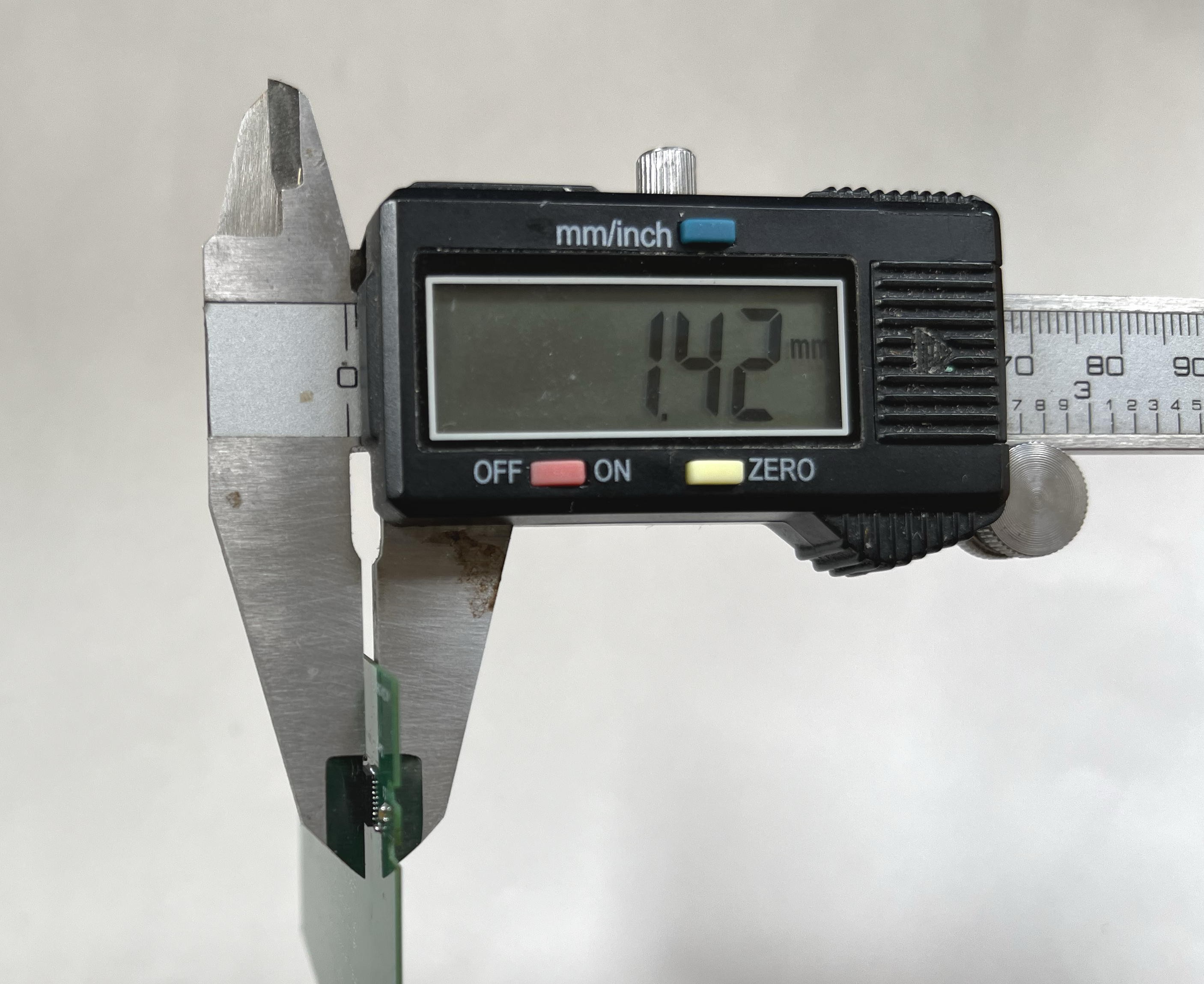
The first has a cut-out for the electronics. It is the thinnest at about 1.42 mm (very close to the ideal of the PCB + 'F096 micro-controller). Unfortunately it's also a bit 'meh' visually.
Next up was to just tape the graphic over the electronics with a cut-out for the USB connector. I don't have a pic with the calipers but thickness is about 1.53mm. It looks better but eventually the paper will wear around the micro-controller and capacitor bumps and it will be ugly. So no go with this approach.
Finally was to use a 4-layer (nom 0.65mm thick) 3D printed spacer designed with OpenSCAD (source and STL attached). The spacer has a cutout for the micro-controller and bypass caps.
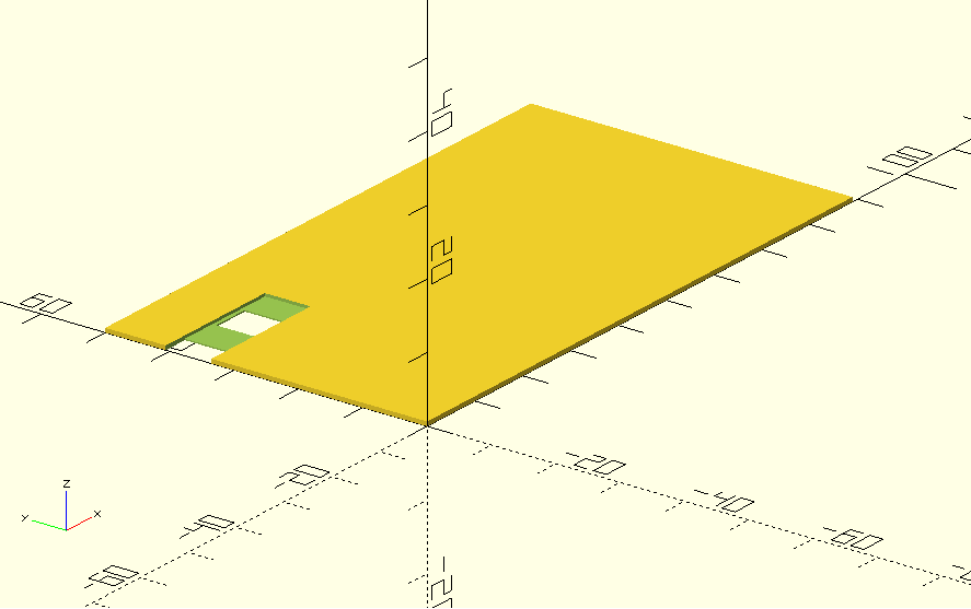
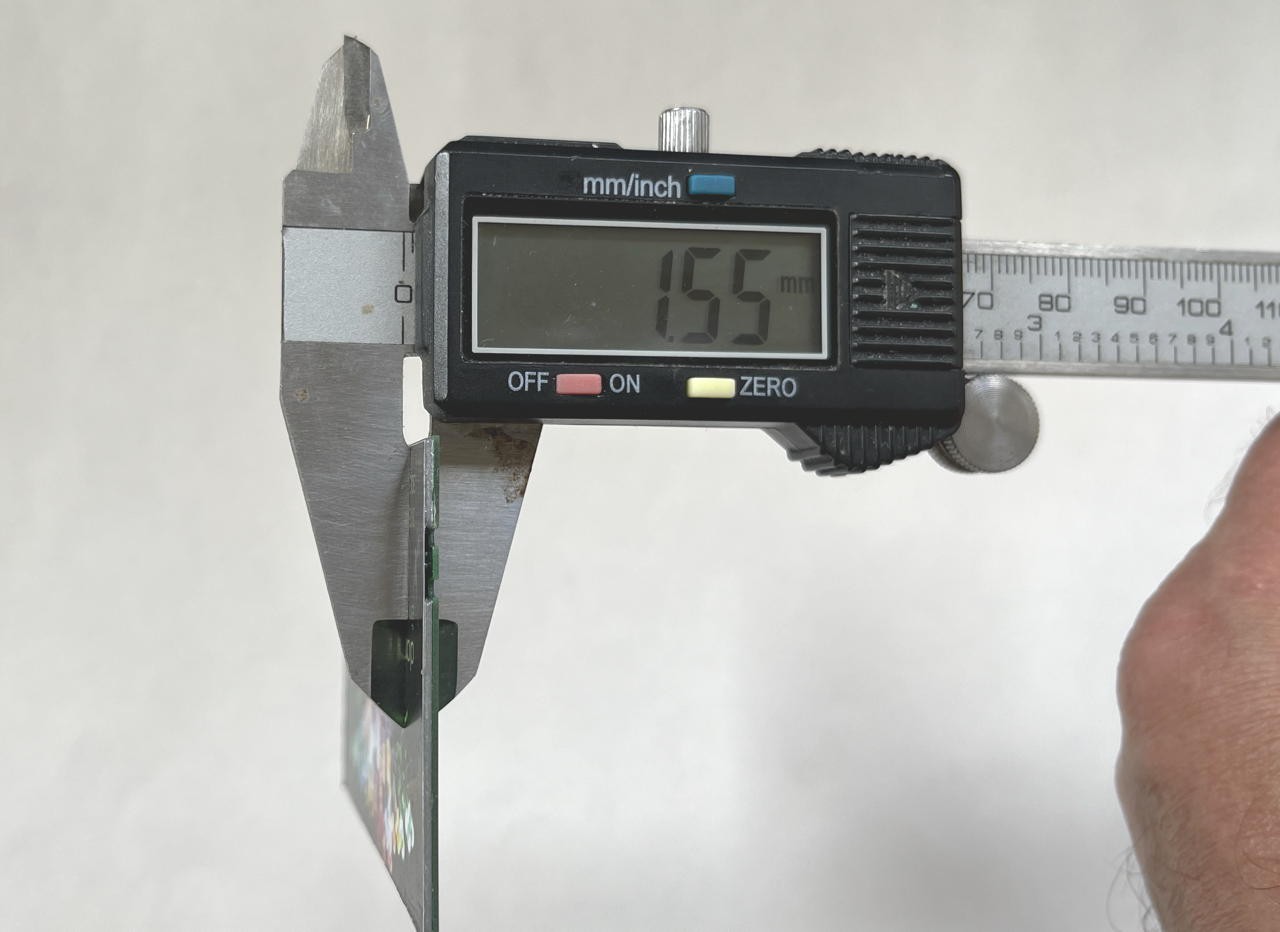
This resulted in the nicest card visually but also thickest at 1.55mm.
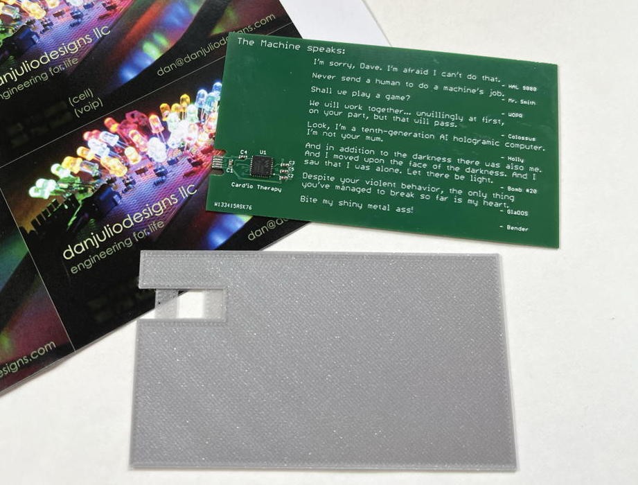
No cuts have to be made in the graphic. Probably this is what I will hand out.
Afterwords I realized that one could also create a much smaller graphic to put in the empty space on the component side above the micro-controller and keep the fun quotes. So dear competition judge, I'd like to claim 1.42 mm thickness :-)
Discussions
Become a Hackaday.io Member
Create an account to leave a comment. Already have an account? Log In.