Porter v4 ran directly from a Lithium Polymer (LiPo) battery, which has an output voltage ranging from 4.2V to about 3.0V (depending on the cut-off of the protection module). In addition, the pre-amp had a passband gain of about 4.3. That means a peak voltage of less than 500mV is still enough to cause the pre-amp to clip. A hard bass slap or a hard strum of all 6 guitar strings can easily exceed 1V peak, which means I really want a supply of at least +/-4V, ideally +/-5V to allow some headroom. This would match up well with the typical 9V supply used by effect pedals.
Unfortunately, my pre-amp and headphone amp chips were both design for low-voltage operation, with a 5.5V max supply. That meant I had to select completely new parts. However, this turned out to be a good thing! I found a new headphone amp chip with really fantastic specs - the Analog Devices (formerly Maxim) MAX97220E. This chip had even better THD (total harmonic distortion) specs than the previous two I was using, plus it enabled stereo output with no DC-blocking caps. On top of that, it had a built-in charge pump to produce its own negative supply (saving me selecting and placing another part). And it was still only $1.50!
One downside is that the new chip uses a QFN (quad flat no-lead) package, which isn't as friendly for hand-soldering or repair. The previous parts were available in SOIC (small-outline integrated circuit) packages, which at least had exposed leads. I've personally found it to be a worthwhile trade, though (and yes, I've hand-assembled a bunch of them with a hot air gun).
I also needed to select a new pre-amp chip. I went back to the trusty Texas Instruments TL072, the "H" variant of which offers lower power consumption and wider output swing than the other variants. The per-amplifier current draw is comparable to the OPA1671, though there are now two amplifiers instead of one. The THD performance is 3x better, but the noise performance is 5x worse; the headphone amp had higher THD and noise than either pre-amp chip, so it didn't really matter anyway! And the overall THD and noise performance are still quite good.
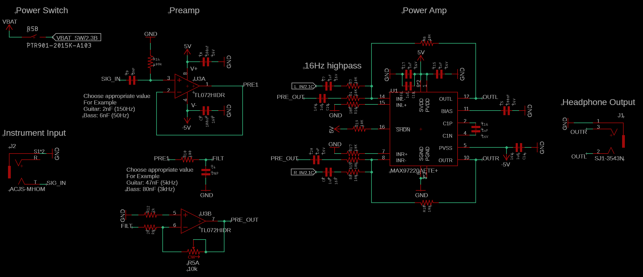
Here's what the audio section of Porter v5 looked like with the new chip selections. Note the -5V supply generated from the headphone amp, which is shared with the pre-amp. Note also that the pre-amp gain is now variable, which helps reduce the likelihood of clipping even further.

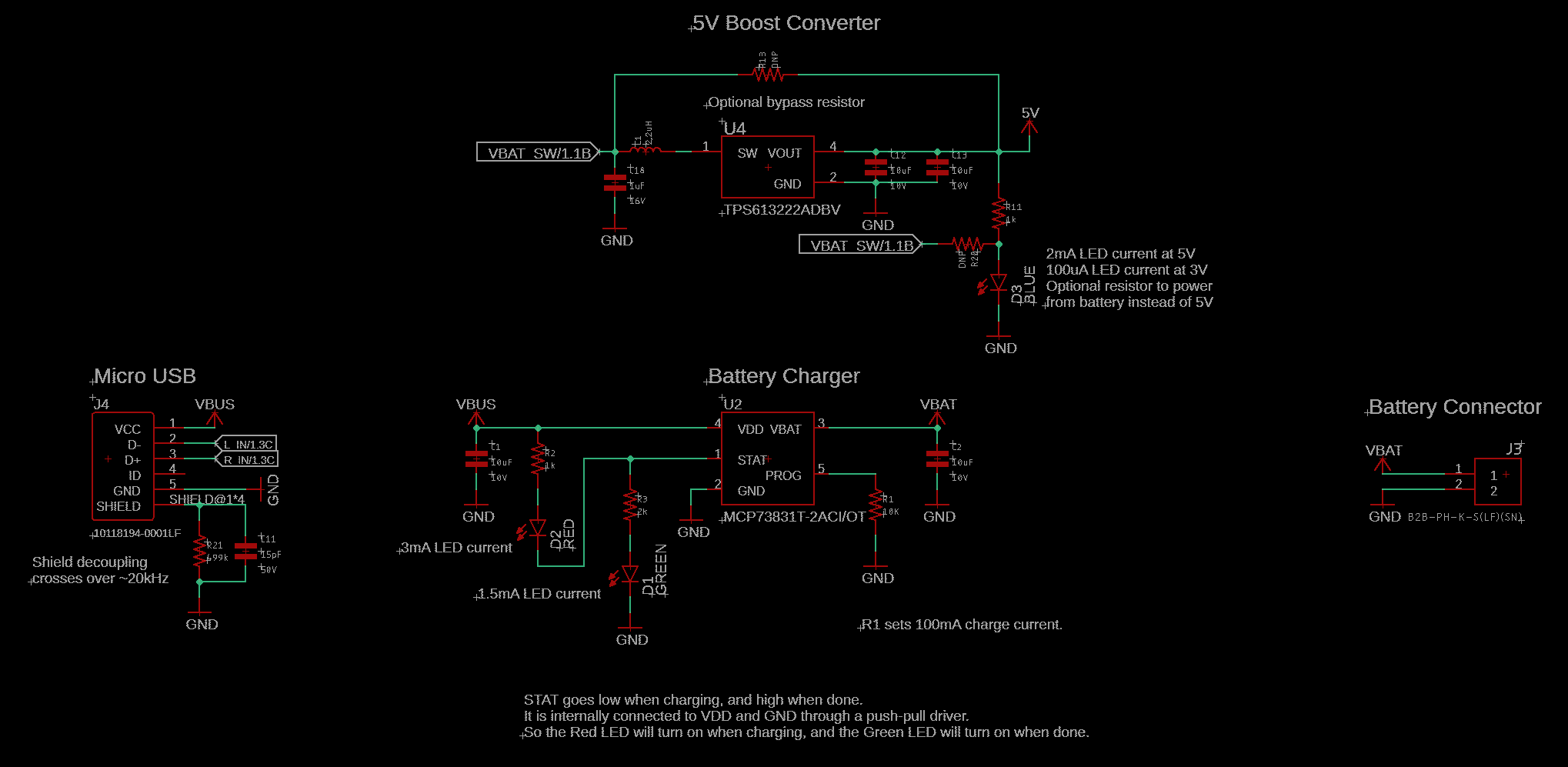
In order to minimize the possibility of clipping as the battery discharges, I decided to also add a boost converter, which would provide a fixed +5V supply. I chose the Texas Instruments TPS613222A, which uses minimal external components and offers great efficiency (82-94%) over a wide load range. I also added a power indicator LED, to help make it clear when Porter is on and operating.
Here's what the power section of Porter v5 looked like with the boost converter added.

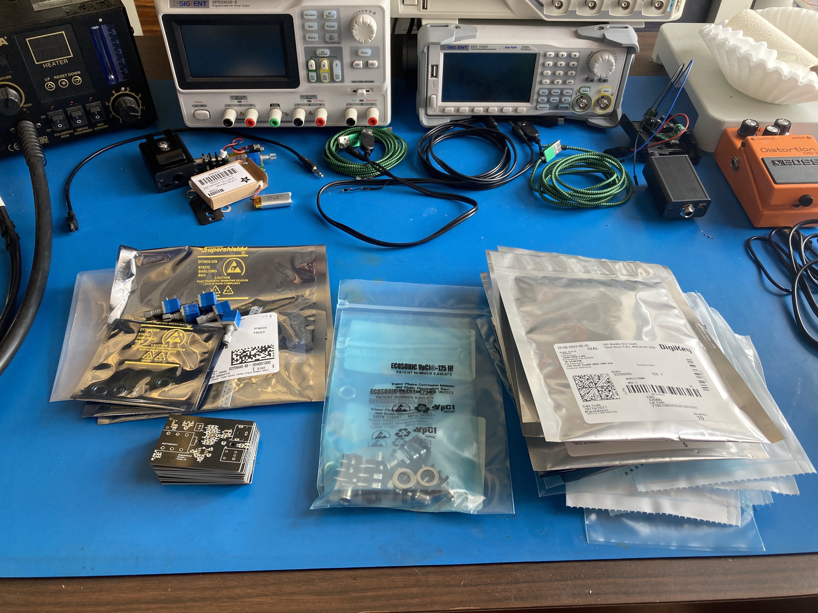
Photos of v5 test build and a close-up of the PCB itself (now in black!):


 Gavin
Gavin
Discussions
Become a Hackaday.io Member
Create an account to leave a comment. Already have an account? Log In.