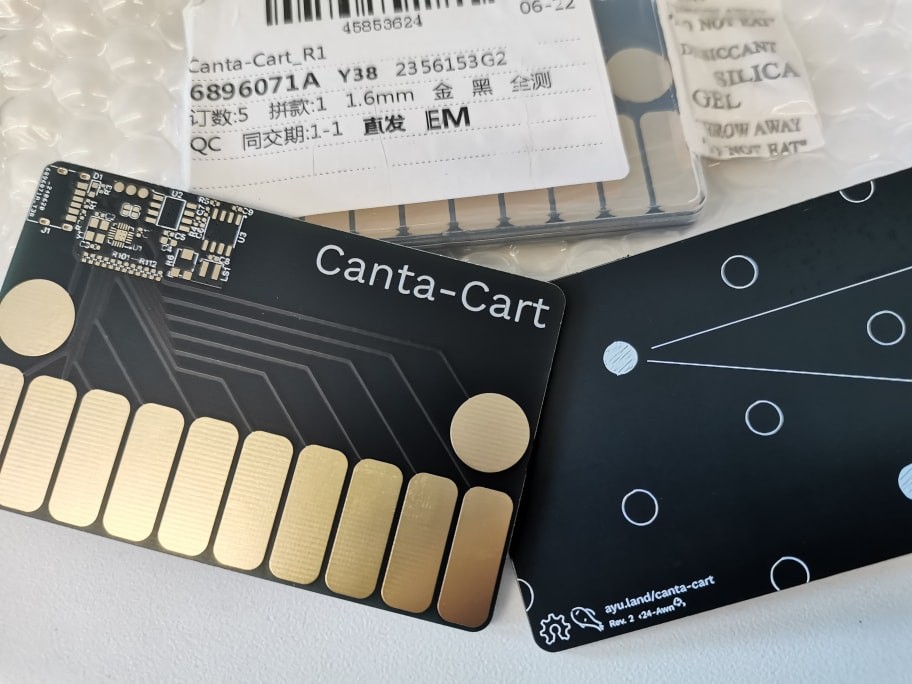
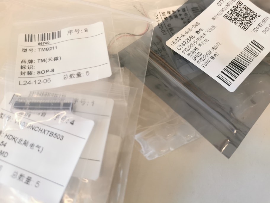
The board and the components have all arrived!
Applying solder paste by hand. I did not rush to a stencil as I felt there were too many moving parts this time — all the ICs on this board I have never worked with before, so I’m actually expecting revisions before a finalised design.
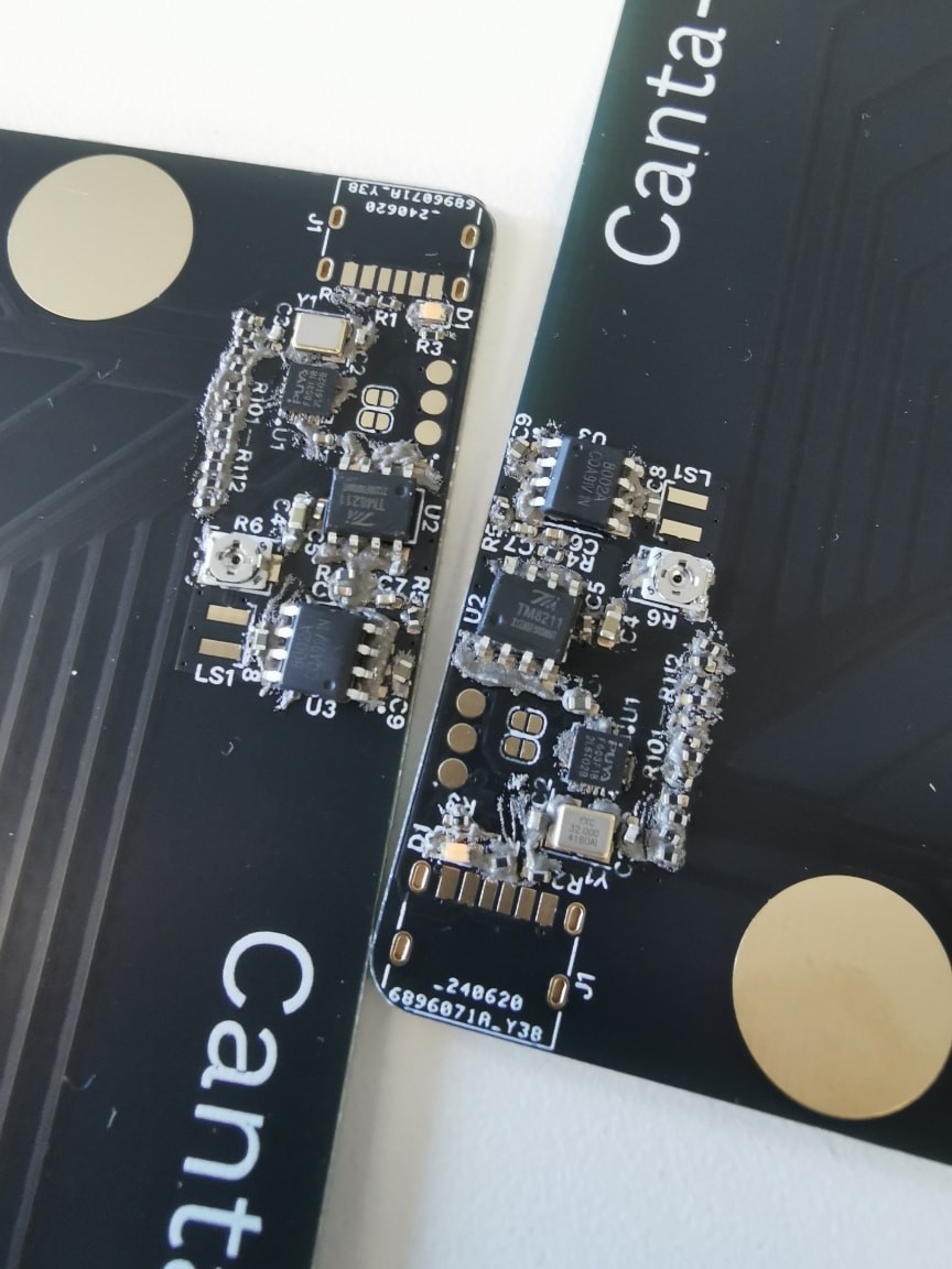
Soldered everything with a hot air gun. 0402 packages are quite a bit naughtier than 0603’s, especially when you’re dealing with a row of black resistors being nudged around on black solder mask! I think I’d switch to a resistor array if I’m doing a revision.
Alcohol cleaning left some white traces of solder flux on the board, so I tried the cleaning agent for the first time. It smelt strange even through a face mask (stranger than any solder flux I’ve encountered), but worked out pretty well.
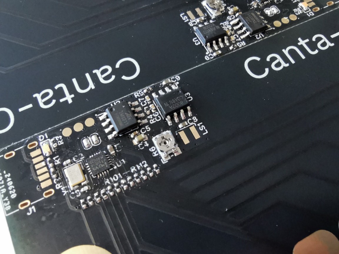
We’re finally ready to launch the MCU and start blinking!
Now comes the twist: I cannot find my DAP debug probe. I remember nothing about its location despite an exhaustive search. This got me stuck for two hours, I guess this is just part of my ordinary ADHD engineering experience. Well, that does not stop me by a least significant bit. Just flash a Raspberry Pi Pico with the debug probe firmware. Voilà! A new probe! Then solder wires to the test pads and the power line. Now there doesn’t even need to be a clip to hold the probes, as these jumper wires can be simply plugged.
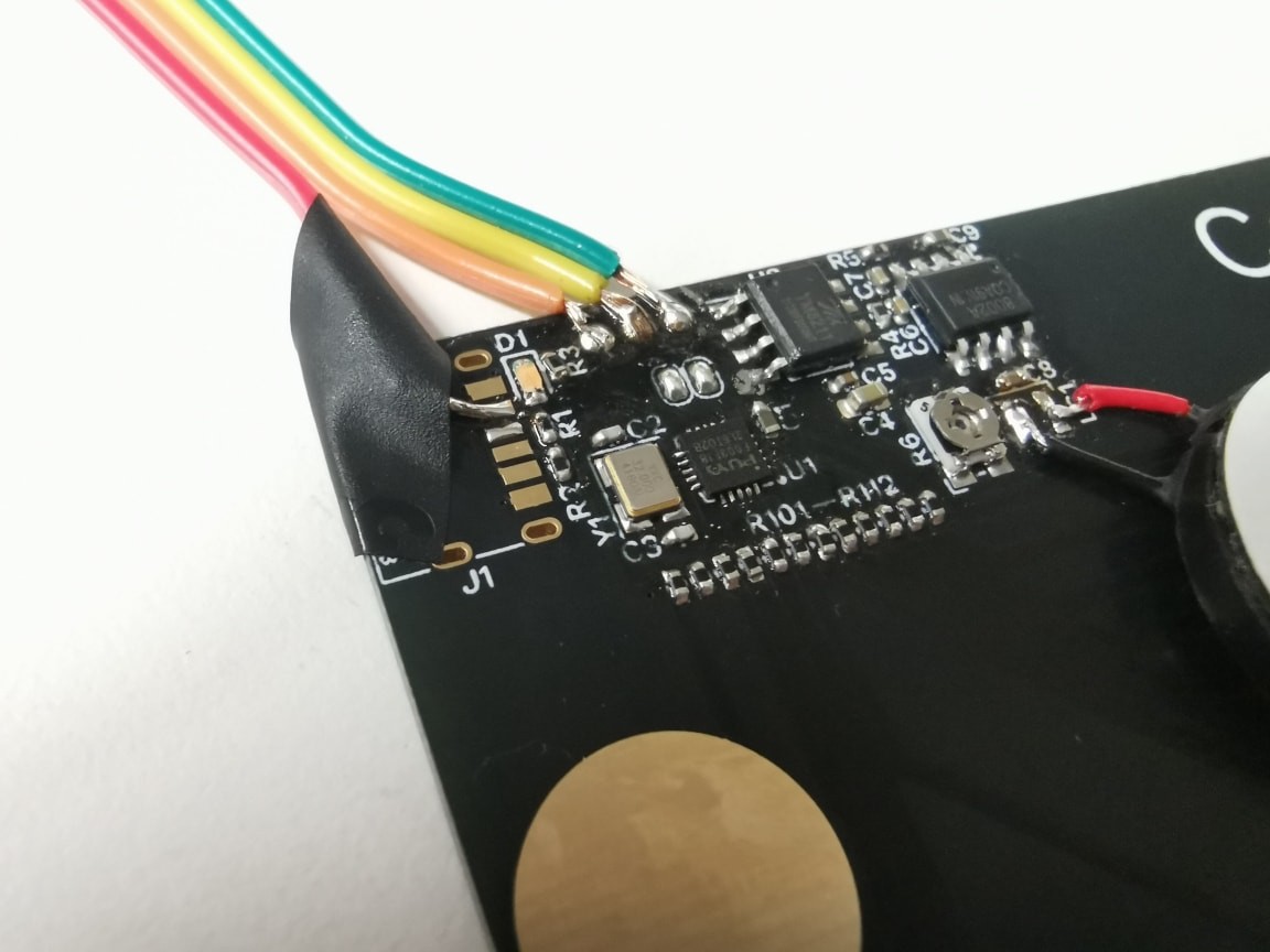
I know, the orange wire fell off very quickly. Once it was fixed, I was able to run pyOCD and flash the firmware through the Pico probe. Does it work? There is no activity LED on this board, but the DMM looks at pin A0 — accessible at one of the touch pads — and says yes, it toggles.
That might not seem like much progress, but that concludes the day well anyway. How will things be going tomorrow? I’m getting curious as I practise on the simulator ^ ^
 Ayu
Ayu
Discussions
Become a Hackaday.io Member
Create an account to leave a comment. Already have an account? Log In.