A fridge compressor as a vacuum pump
Here is a fridge compressor tranofrmed intoa "smart" vacuum pumps.
And the evidence that it works for fiberglassing a V tail of ta glider.
The wing is into the Nespresso vacuum bag !
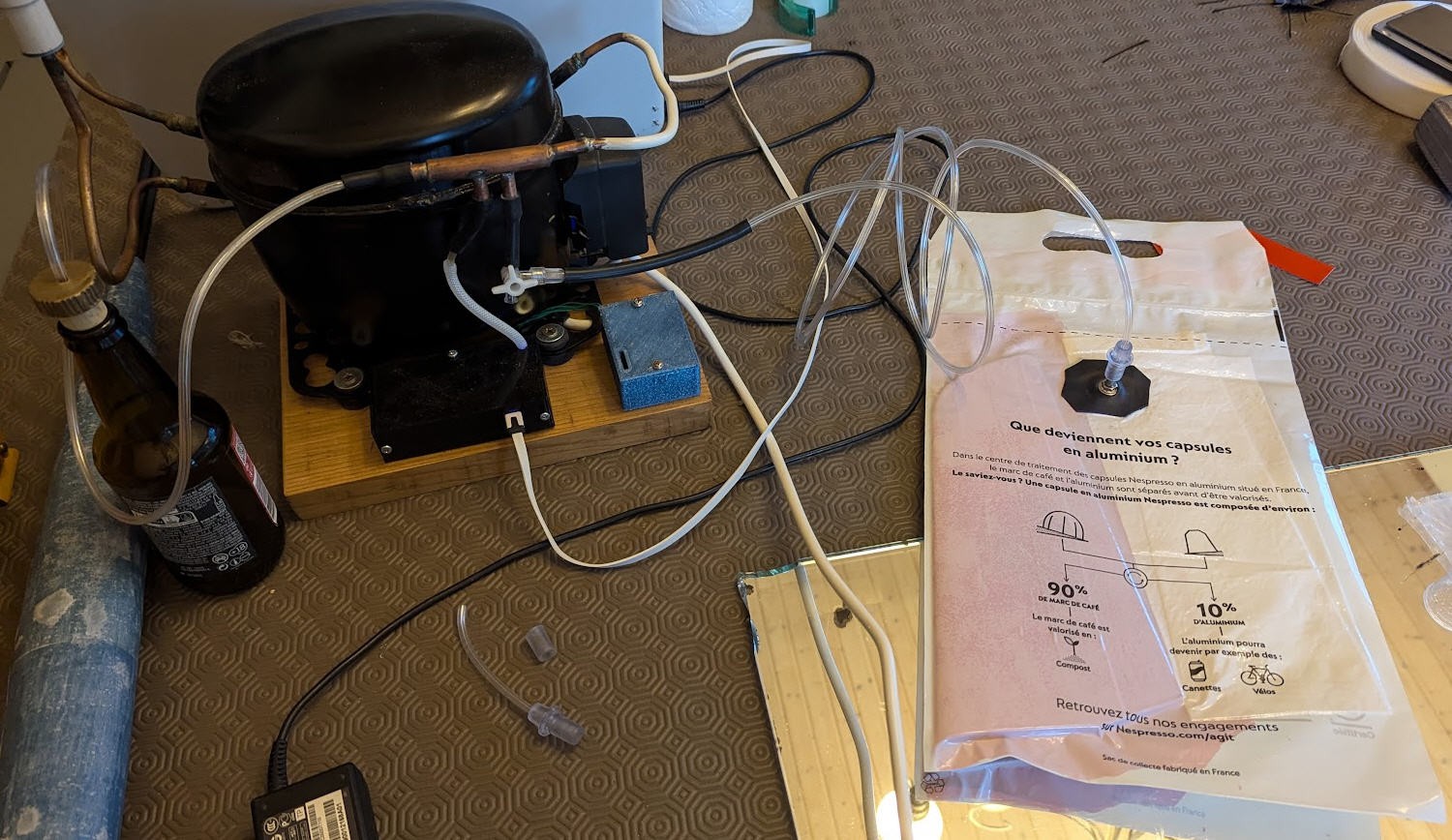
And a short video showing the start of the vacuum succion with a much bigger vaccum bag:
So, a friend of mine gave me this refrigerator compressor:
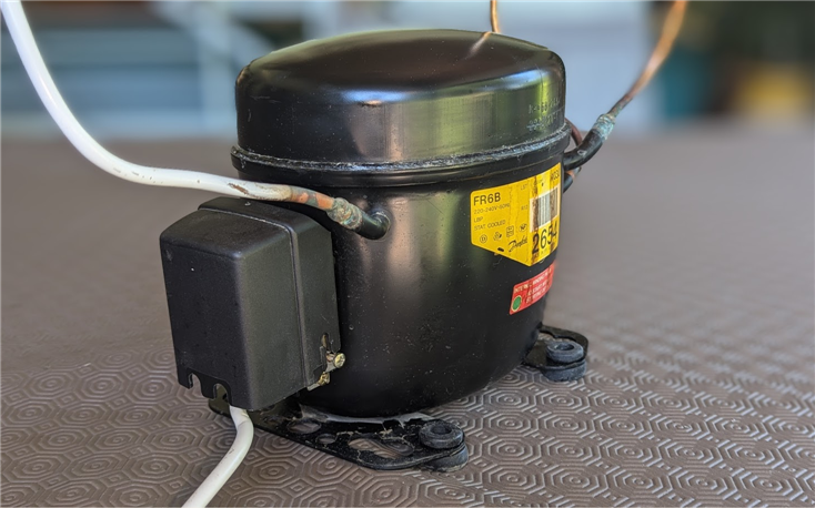
I removed the lid and found a so called "starter relay".
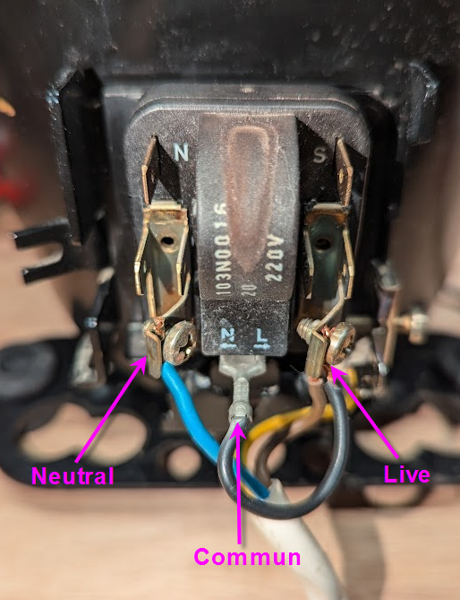
So I just had to apply MAINS voltage:
- Neutral on N pin
- Live on L pin and C pin
Then I tested it and the motor worked producing a strong vacuum.
My very first finding was that a fridge compressor has a very weak air flow. Its CPM (Cubic Feet per Minute) is very low. But who cares for my application ? I just want to empty a vacuum bag then keep the pressure down. So it should work.
Vacuum produced is strong and even very strong. After searching on the internet I found that this kind of device would deliver -27 inch of mercury...

What is -27 inch of mercury into units understandable in european union ?
Well it's almost 1kg/cm^2

This means that every cm^2 of my foam wings will receive a 1kg load.... If my wing was 1m^2 it would receive 10000 kg on each side. For sure the foam would crash.
As a consequence:
- vacuum produced by the fridge compressor is more than enough for vacuum bagging applications
- a regulation system must be used to avoid too much pressure on the foam
This regulation system will take care to start and stop the compressor when pressure is too high or too low.
So we will try to start/stop the compressor...
Starting/stopping a fridge compressor
A fridge compressor is composed of a motor equiped with two coils.
- a "run" coil which must be powered to run
- a "start" coil which must also be powered but only to start the motor during less than 2s
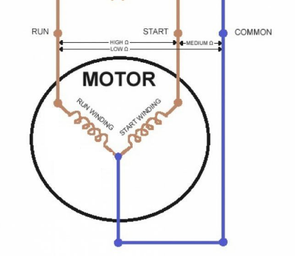
Note that, to know which coil is the run and which is the start, you have to measure the resistances with an ohmmeter as indicated on the above picture.
To apply the short pulse on the start coil a "starter relay" is used.
The "starter relay" of my fridge is labelled 103N0016 and was produced by Danfos. I found the datasheet which showed that this relay is not a relay but a more tricky device.
Here is its schematics
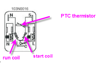
Obviously this device does the job as the motor starts... but I very soon discovered that if I start then stop the motor it would not start again. And this is critical as, while starting, the run winding is powered but the motor is "blocked".
To understand why this is occuring we have to look carefully at the inner components of the "starter". You can see that a PTC thermistor is shunting the run and start coils (N side).
PTC thermistors are temperature-dependent resistors based on special semiconductor ceramics with a high positive temperature coefficient (PTC). They exhibit relatively low resistance values at room temperature. When a current flows through a PTC the heat generated raises the temperature of the PTC. Once a certain temperature (Curie temperature) is exceeded, the resistance of a PTC rises significantly.
So that, when starting at room temperature, the thermistor is more or less a "shunt" passing the full power to the start coil thus starting the motor. Immediately after the temperature rizes and the resistance value also thus limiting the current into the start coil and virtually disconnecting it (which is expected)
But, if I stop and restart the motor, the thermistor will still remain (very) hot, its resistance is high, the start coil is "disconnected" and the motor does not start leaving it in an unsafe condition (run coil powered but motor stopped).
To avoid this behavior we have two solutions:
- use the starter but wait 30s to recover room temperature if you want to restart it
- do not use the starter and replace it by two independant relays. One for the run coil the other for the start coil
My electronic board will be equiped of two relays to allow implementation of these two solutions !
Electronic board to automate the vacuum pump
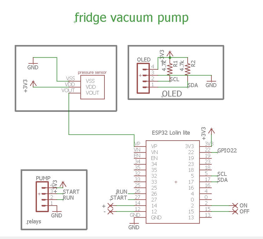
Schematics
Schematics of this board couldn't be more simple.
- An ESP32 microcontroller will handle all the logic and communication with smartphone over Bluetooth Low Energy
- two relay boards will handle the motor coils
- an OLED display could be used for debugging
- a pressure sensor will convert vacuum level into a voltage read by the ADC of the MCU
Pressure sensor
I choose this kind of sensor easily available on aliexpress:
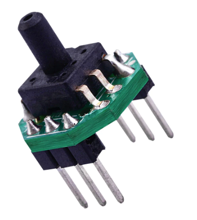
Many references does exist, you have to select the right one: DC0.2-2.7V Barometric Gas Pressure Sensor Transmitter PCB Module Vacuum Negative Pressure -100 to 0kPa
- power is DC 3.3V
- pressure range should be for vacuum between -100kPA to 0 kPA
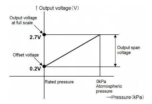
With a 3.3V device the output signal will be between 0.2V to 2.7V which is perfect for the ESP32 ADC levels
Datasheet was hard to find, but here it is : XGZP6847A Pressure Sensor Module
And here is its response when applying vacuum:
PCB
Routing this simple schematics was fairly easy.
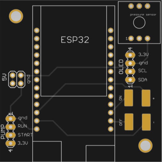
PCBWay kindly proposed to sponsor this project and has produced professionnal looking boards.
Quality is, as usual, excellent and the black silkscreen beautiful !
If you want to get one, simply follow this link : Vacuum Pump PCB @PCBWay
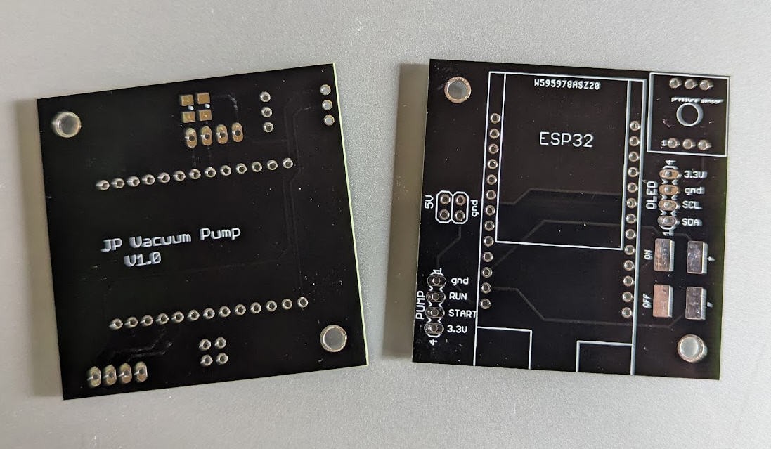
Soldering this PCB took almost 5 minutes! I even didn't solder the I2C pull up resistors and it worked !
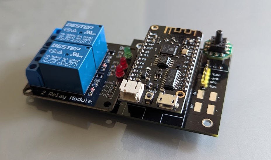
Now comes the easy part: the software
Software
Firmware of the ESP32 could have been extremely simple as we basically just want the following features:
- start the pump
- read pressure
- stop the pump if highVacuum is reached
- resume pump if low vacuum is reached
But I wanted something a little more user friendly:
- smartphone application with BLE communication with the ESP32 (optionnal)
- monitoring of pressure and user interface on the smartphone (optionnal)
- touch pads on the PCB board to run the device without the smartphone (optionnal)
- LCD screen (optionnal)
Finally software is thus divided into two parts:
- ESP32 firmware
- Android Application
Both are available into my github pages here : Vacuum Pump @github
The system can work without the android App.
Firmware is handling a finite state machine which is easy to understand:
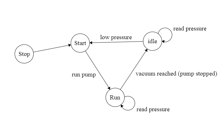
Man Machine interface (MMI) can jump to "start" or "stop" status into this graph. When booting the ESP32, the status is set to "Start" allowing the pump to immediately enter into a "vacuum" cycle without any user intervention.
MMI can also set "low" and high" pressure thresholds used to control the vacuum. User can interract with "ON", "OFF", "+" and "-" touchpads on the PCB.
"+" and "-" pads will respectively increase and decrease:
- highPressure threshold when pump is stopped
- low pressure threshold when pump is into another status (start/idle/run)
LCD displays real time status of the pump:
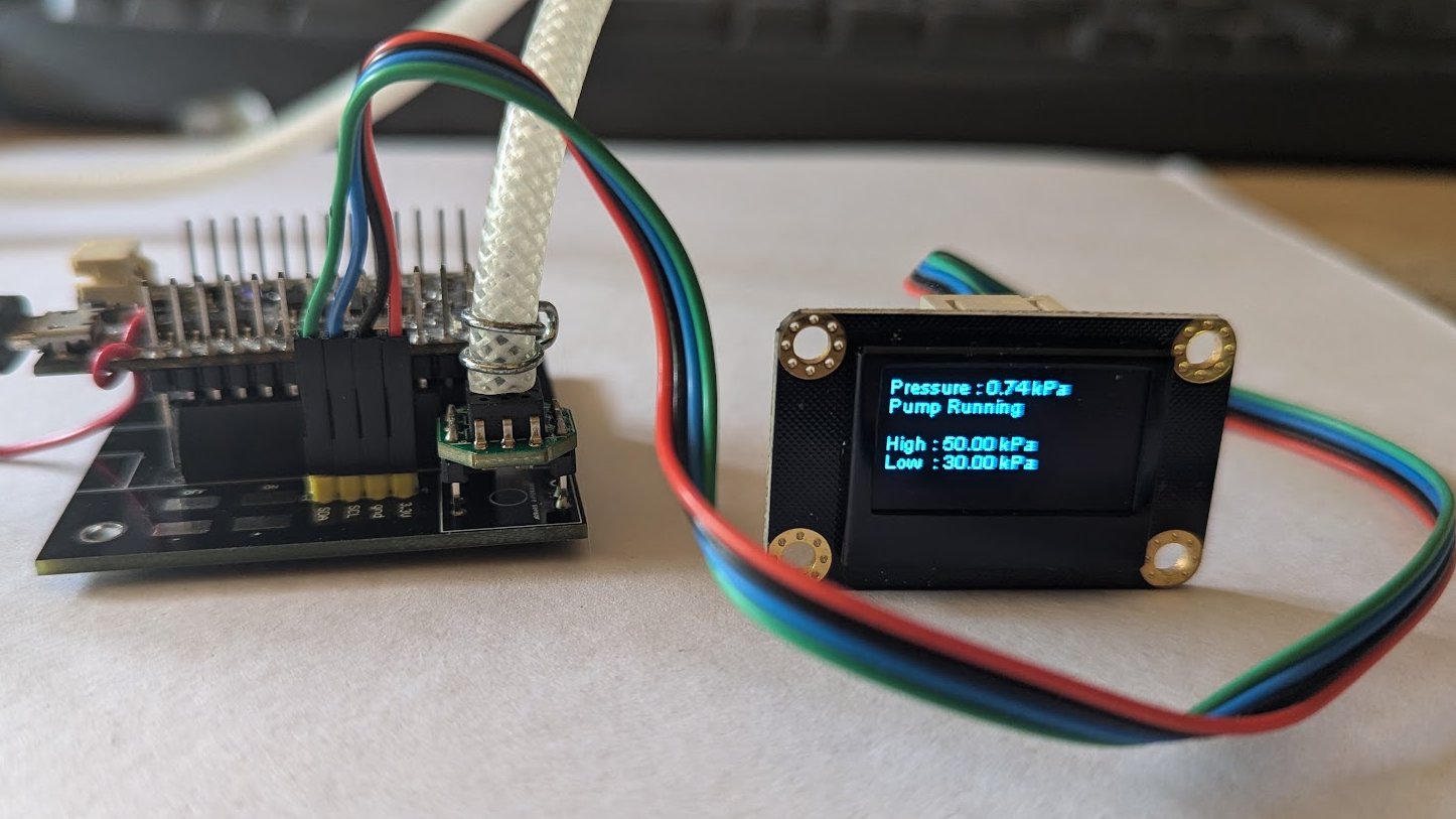
But being an Android lover, I do prefer using my phone! This is the reason why you won't see the LCD in my final setup although the code runs and can run even if the phone is used !
Andoid application communicates with the ESP32 using Bluetooth Low Energy proctocol. This is very handy as no "connection" or "pairing" has to be done. Everythng is handled via the protocol itself as the ESP32 will "notify" its capabilities via BLE.
So here is the screen that you should see on your phone when the app is running:
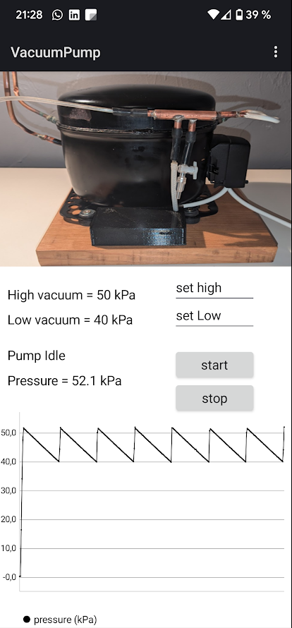
As you can see, I monitored 7 cycles where pump started at 40 kPa and stopped at 50 kPa.
I created a small leak in order to let the vacuum decrease, thus the "saw blade" shape of this curve.
Pressure is very cleanly stabilized and you can change thresholds when entering values in the "set high" or "set low" text boxes.
And if you want to see the system into action, here it is.
Nice setup isn't it ?
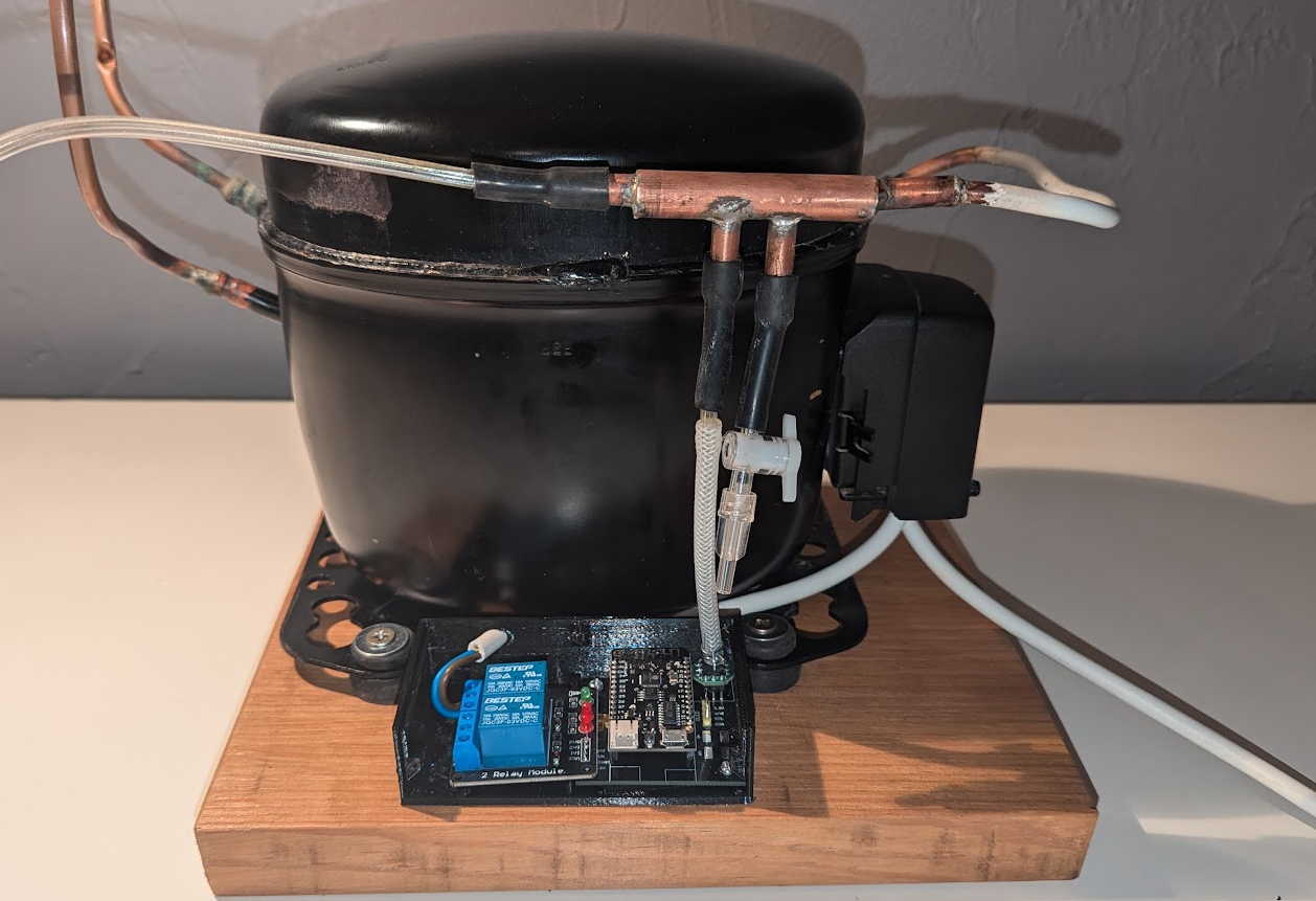
Final setup
Connecting the board to the pump is fairly easy
Just build (or buy) a T shape coper pipe that you have to put into the intake. Connect one side of the "T" to the sensor, the other one to your vacuum bag. If you want (I did it) add a purge tap.
Fix the https://www.thingiverse.com/thing:6682282 with a pair of 2 or 3 mm screws.
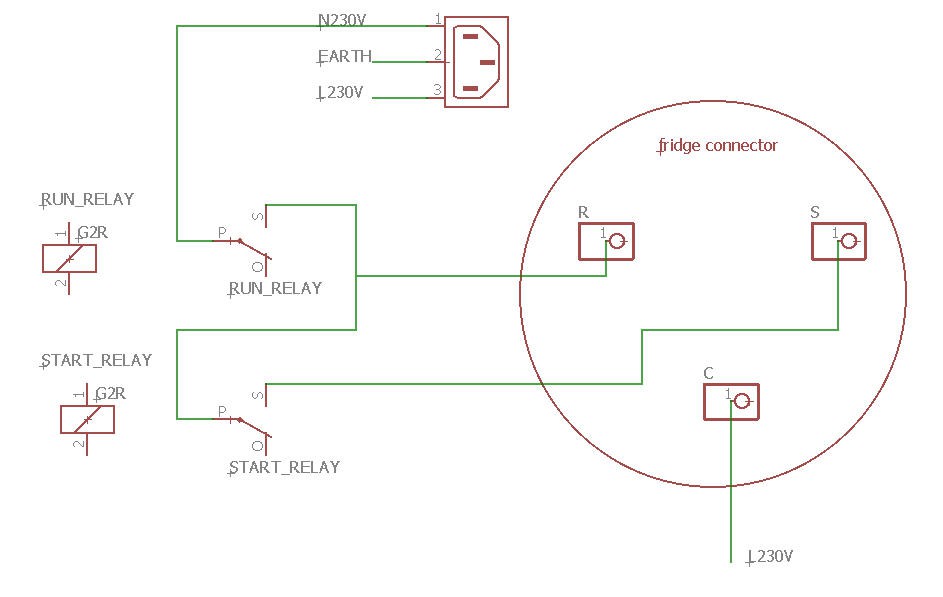
If you connect the motor without the starter (thermistor) then you should use the two relays of the board like this:
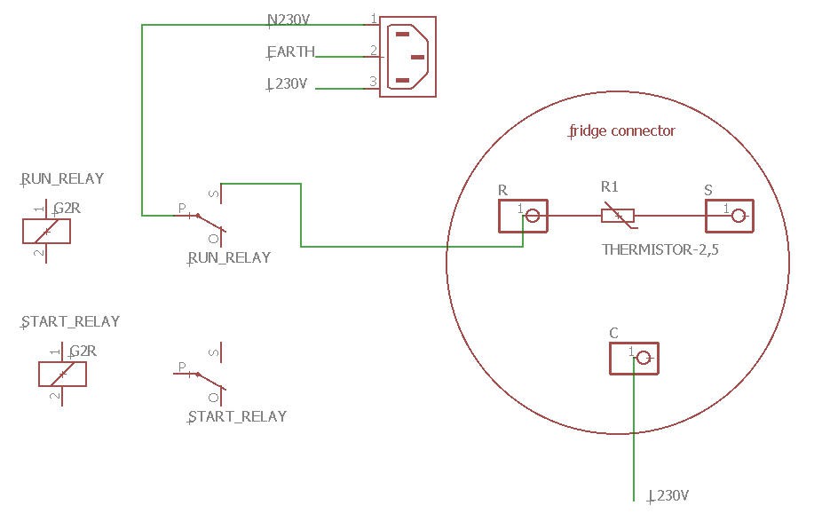
If you prefer to reuse the starter device (thermistor) then the connections are even simpler:
I have tested both solutions and the most reliable is without the thermistor. Without it, the "recovery time" between start/stop and restart can be decreased to 10s compared to 40s with the thermistor.
In any case, if you don't understand these schematics do not try "at random" .... MAINS power is dangerous and can even be lethal. Don't play with it.
Now connect a USB cable to your ESP32 and you are good to go.
Long duration test and some modifications
Willing to use this device for vacuum bagging, I would like it to run during more than 10 hours to keep vacuum into the bag while the epoxy is curing.
So I launched this kind of test:
- run it with a little leak to trigger the fridge compressor once every 3 minutes
- keep a vacuum level between 20 and 30 kPa
And then came the first problems... Randomly after a few hours the ESP32 crashed... and never recovered.
I tried a lot of things to avoid this crash:
- add a voltage regulator devoted to the relay board
- add a capacitor to "store" 3.3V
- add a totally new power supply for the relay board
But nothing worked
Tests where performed during night, sometimes it worked sometimes it crashed.
I increased the leak to have more start/stop of the fridge. And finally added also "securities" into the code. But the ESP still crashed.
Finally after a week of tests in these conditions the start relay died... And then I had an idea : could it be EMI ?
Electromagnetic interference (EMI) is unwanted noise or interference in an electrical path or circuit caused by an outside source. It is also known as radio frequency interference.
I opened the relays and cleaned the contacts. And here is what happens when the start coil is disconnected :
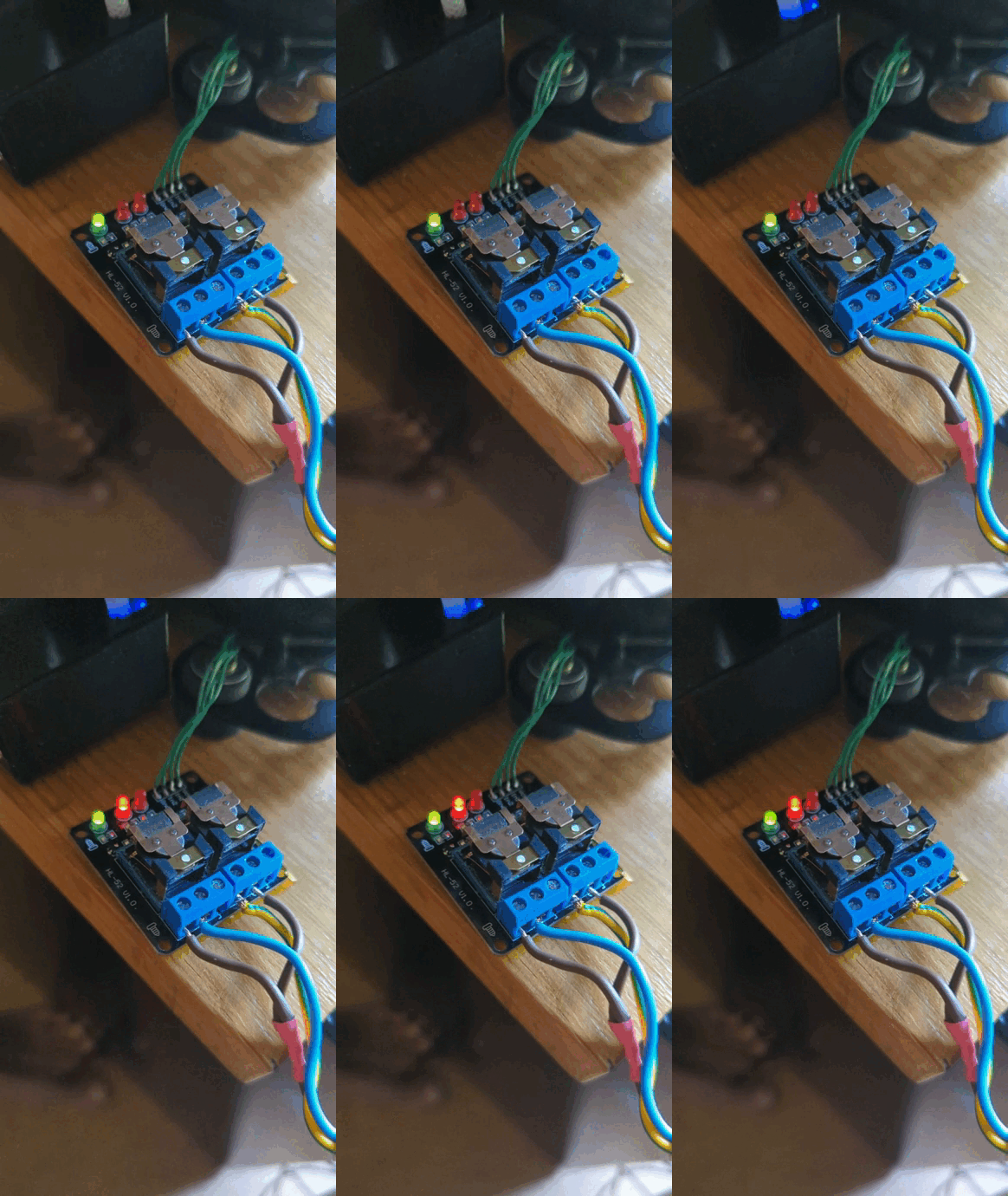
As you can see this big spark is quite impressive. The relay being close to the ESP32 it was enough to crash it randomly.
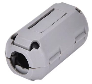
So finally I unsoldered the relay board from the ESP32 PCB and reconnected it with 30 cm wires. I also added a small ferrite around the 4 wires connecting both boards.
And you know what ? It works now.
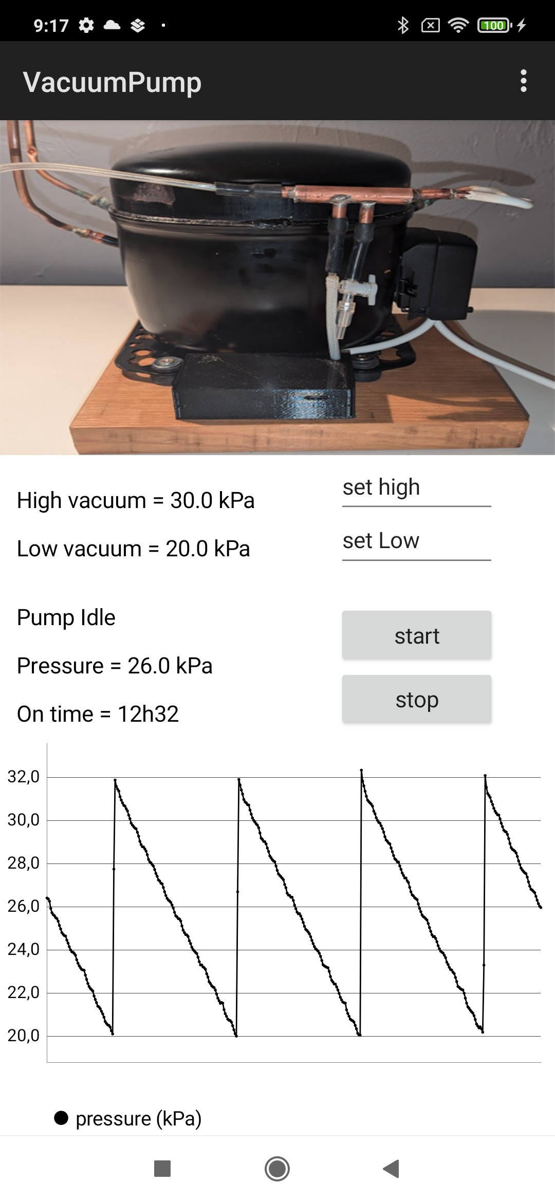
This is the result of the latest test performed during 12h30. Everything is fine now and no crash detected !
However there is still one remaining problem : the start relay contacts will progressively wear, leading to no contact at start... which is a very bad situation for the compressor (powered only with the run coil and stalled...)
So I have added some "security" into the code. I monitor the vacuum level during start, if vacuum increases everything is fine. if not... then a problem occured. I retry 2 more times and if the problem is still there, then I go to the "Alarm status" and stops everything until the oprator presses again on the start button.
Here is how it looks like on the phone:
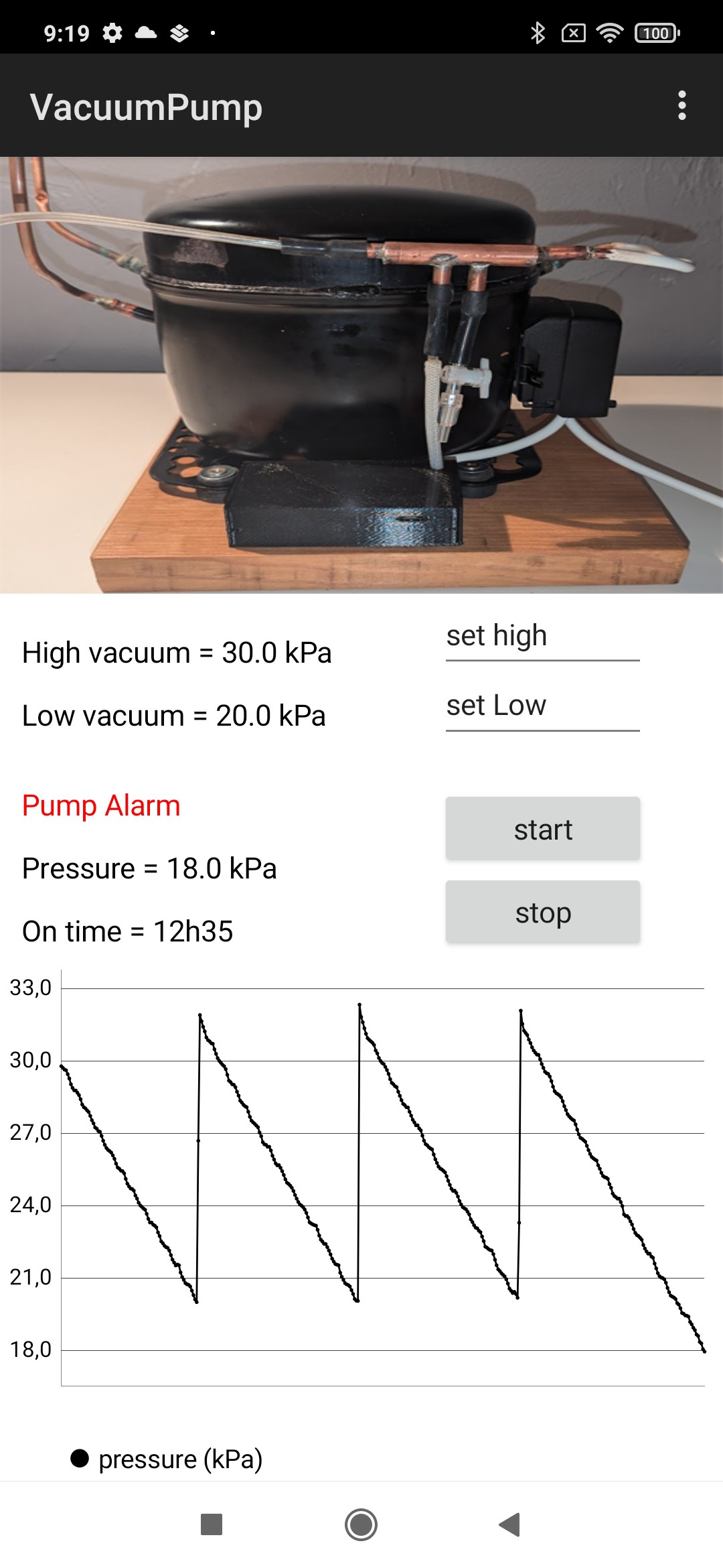
As you can see we are "under" the 20 kPa low threshold, the pump tried to run but failed... (Mains plug was disconnected !)
If you reconnect the plug and press the start button the pumps recovers
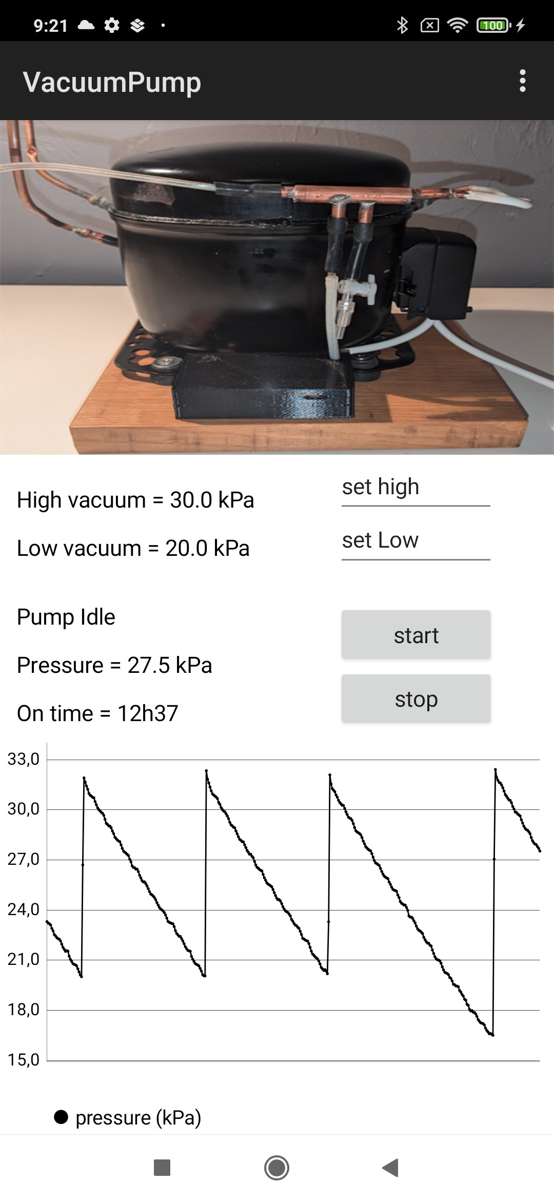
This may look like a "gadget" but trust me it is not... If you don't detect this kind of behavior the fridge will over heat and can be damaged although there should be an internal protection (Klixon thermostat) to prevent the pump to catch fire...
A Klixon is the trade name of a temperature-sensitive electrical switch used in interlock circuits of power supplies and magnets that opens when a certain temperature is exceeded. Some are rearmable some not...
I have tested this code several times and it works very well preventing the motor to overheat and the kixon to trigger.
Limit arcing issues
One solution to limit arcing issues on an AC contact is to add a snubber. It's a simple RC filter that you solder in parallel to the contact.
Choosing the right combination of R and C values is quite "tricky". My advice is to read this very good explaination.

Frankly speaking, even with this snubber installed, the spark is still present. So be prepared to use a spare relay when the first one will be worn out !
 JP Gleyzes