Close
0%
0%

Low cost 10 MHz OCXO addition to TS-930

Low cost 10 MHz OCXO addition to KENWOOD TS-930
as a high precision frequency standards!

Similar projects worth following
113 views
Sometimes we can find very low price (surplus from wireless base station?) 10 MHz OCXO at auctions and eBay. The SO-1 and SO-2 are the 20 MHz TCXO and we need 20 MHz, not 10 MHz. The handy way to get will be, simple PLL circuit or analog frequency doubler circuit with class-C operation amplifier. This time I took another to obtain 20 MHz signal from 10 MHz OCXO and also confirmed working with TS-930. This modification can be applied to, also TS-940 and 950.

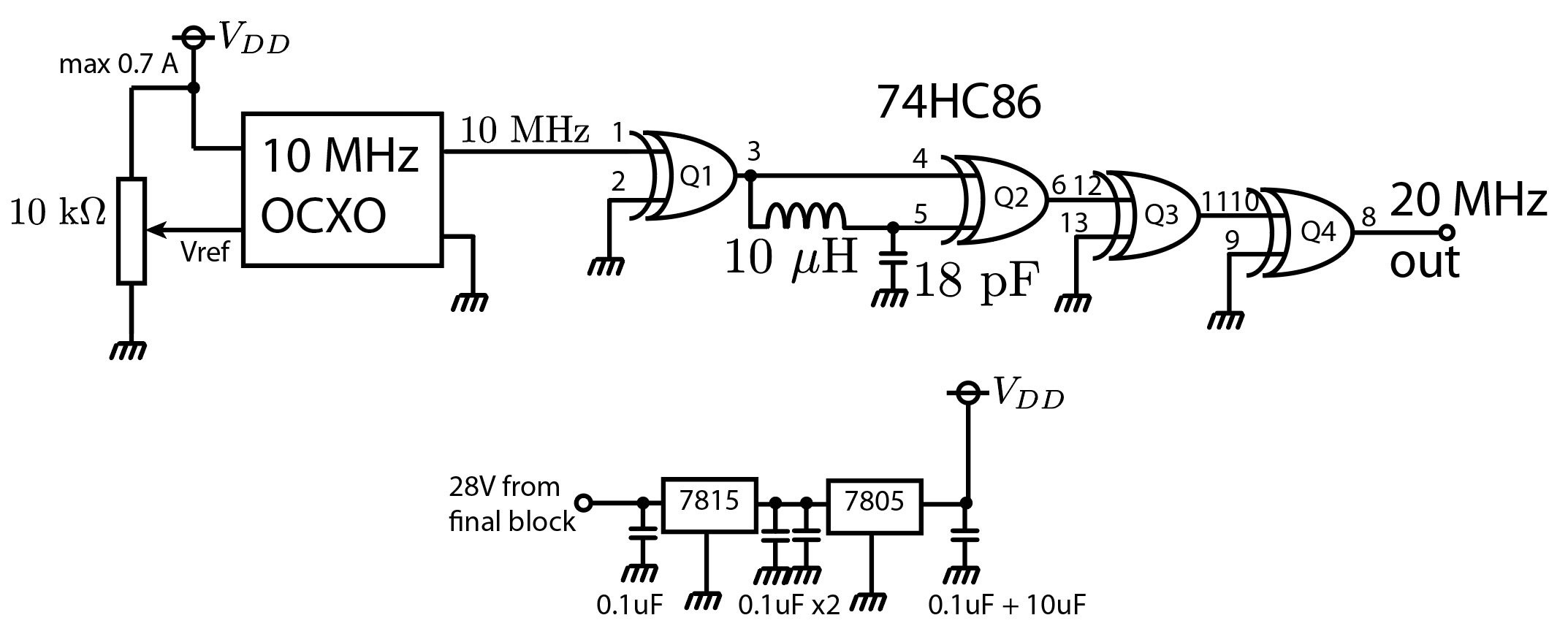
Above is the whole schematic. The key is the frequency doubler by Q2. Q1, Q3, Q4 are just buffer made of vacant pins of 74HC86.You may not believe this simple circuit produce 20MHz signal? Here is the proof!
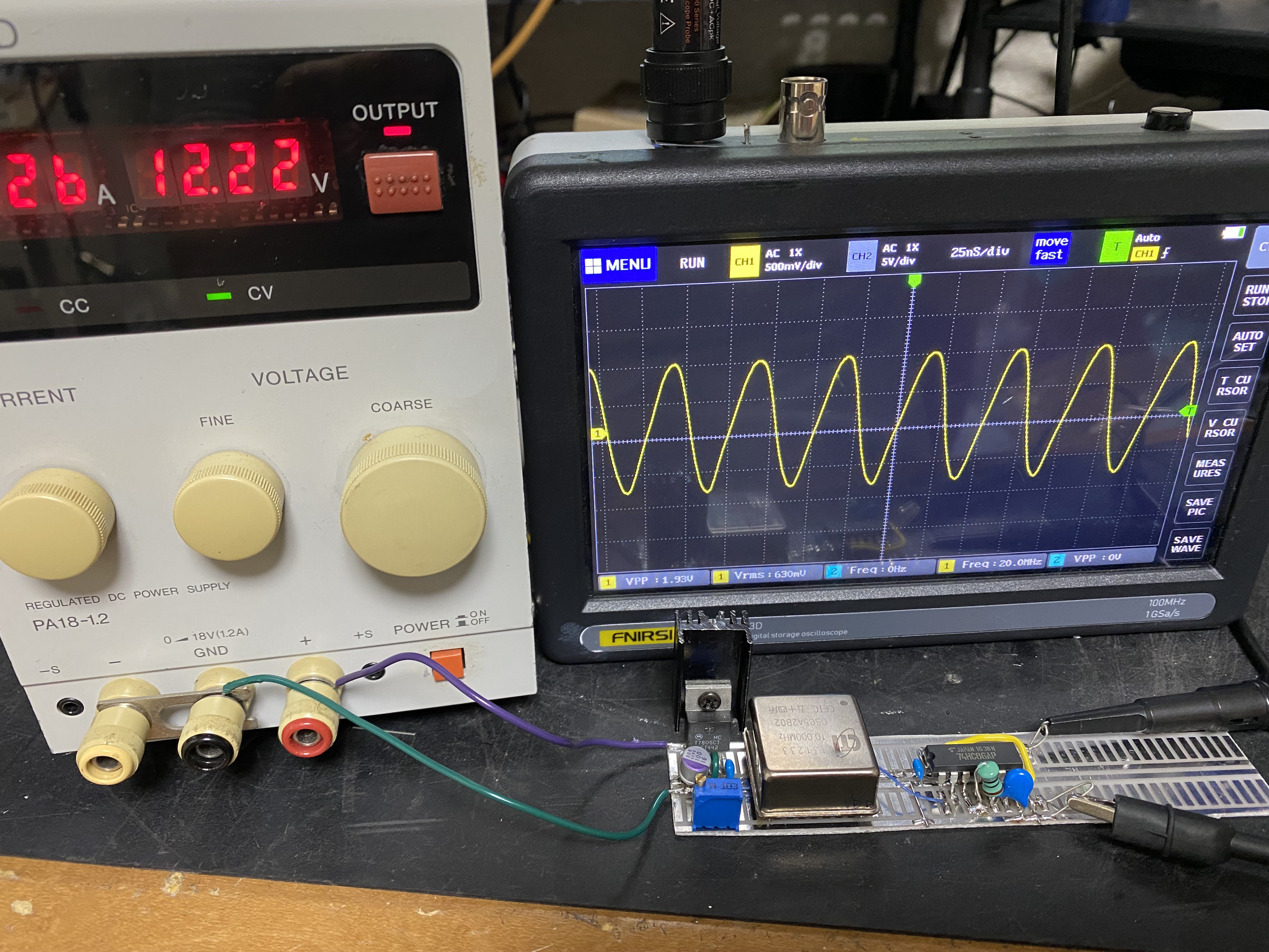
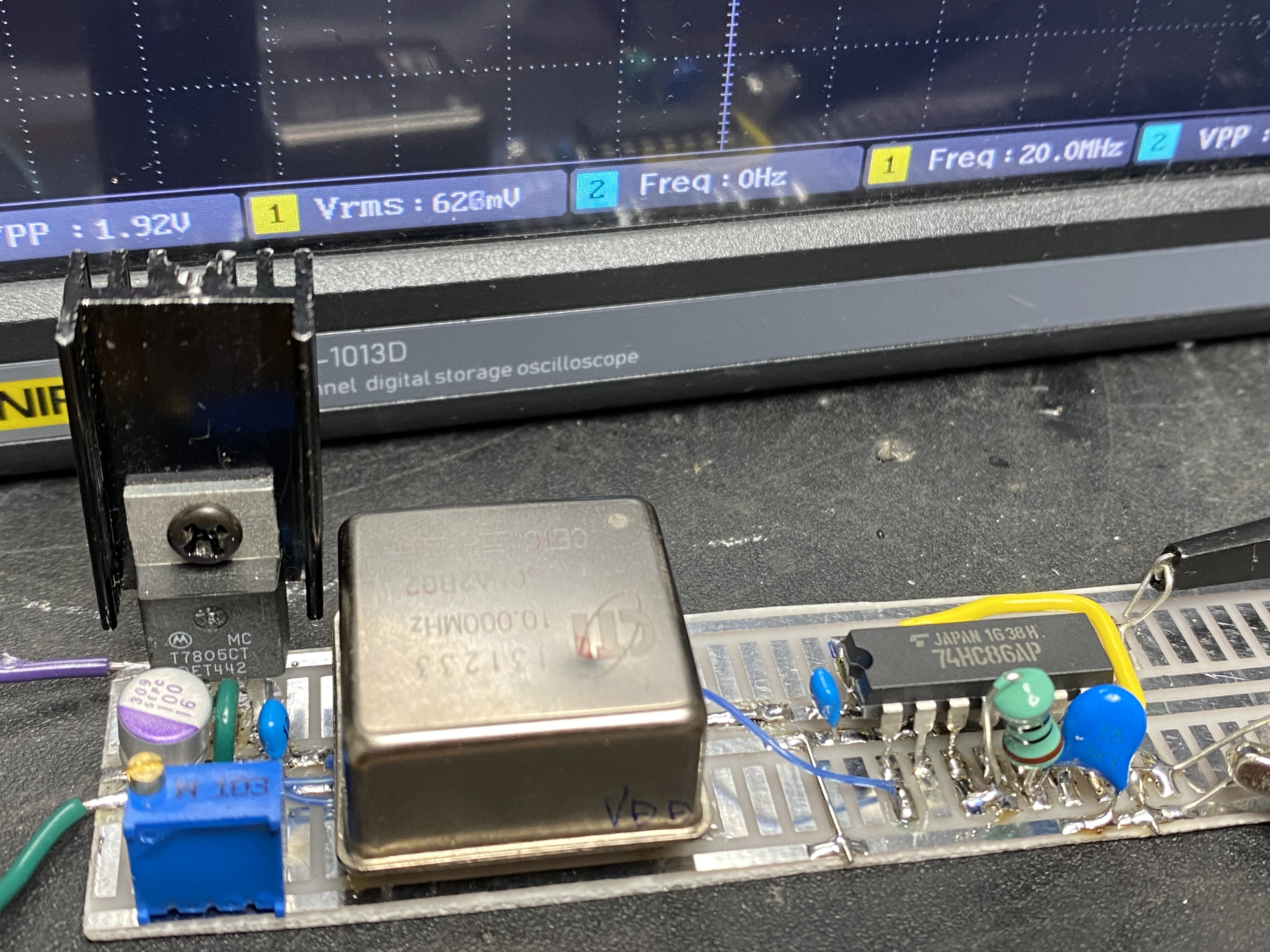
The frequency calibration can be done just by 10k trimmer.

The maximum current draw of OCXO is 0.7A and I could not find good place to get 12V (or less) where has enough capacity for supporting this draw, so the voltage source is obtained  from final block, where 28V/20A capacity. The 5V is generated through two-stage voltage regulator. Single stage regulator excesses the maximum rating of 78xx series heat dissipation and the two stage can divided heat generation in two parts.

The 20 MHz out can simply connect with “SO-1 terminal” of TS-930. The actual implementation is just shown below…
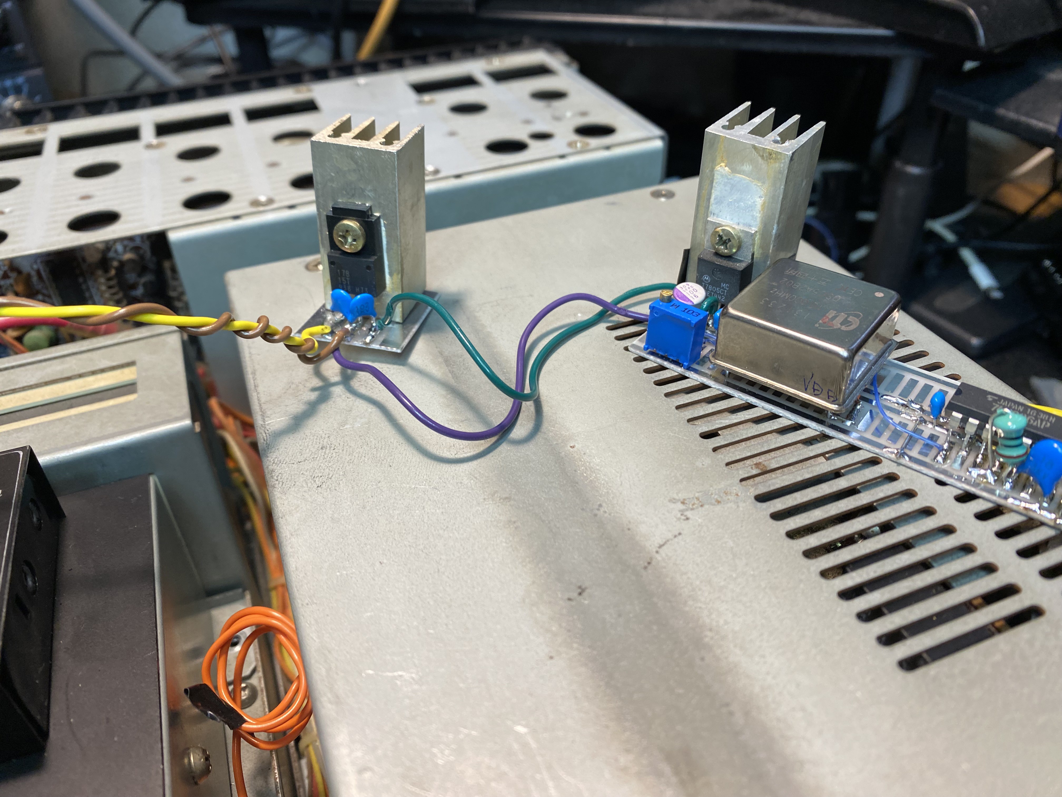
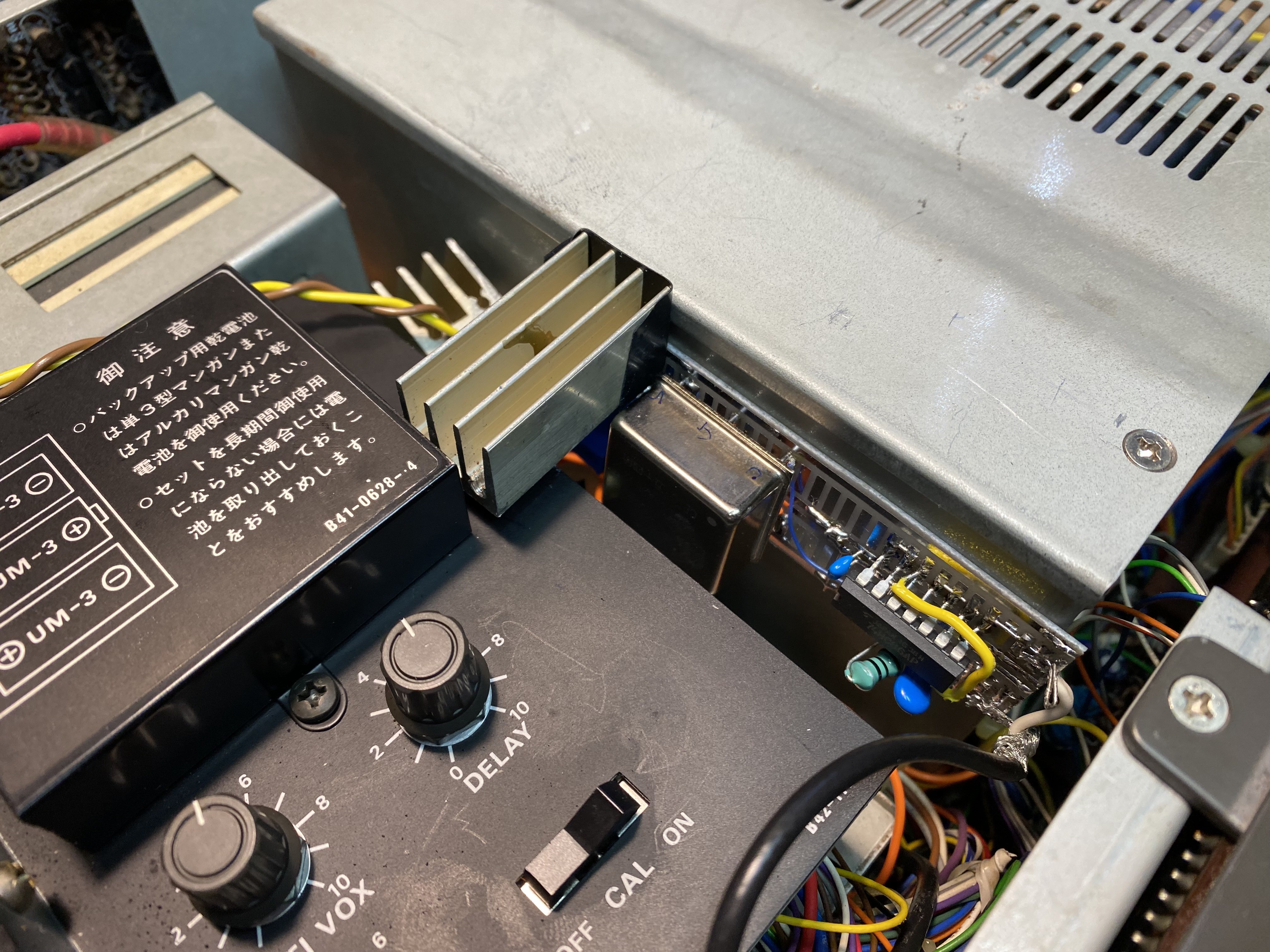
The TS-930 does not have much room to put any items, so the whole unit is inserted just besides antenna tuner opening.

Please note that the OCXO requires, at least, two minutes to stabilize. But a few minutes later from cold-start, your TS-930 will get super high precision frequency standard!

and it works,,!

  • 20 MHz clock input terminal preparation

    kodera2t06/28/2024 at 10:40 0 comments

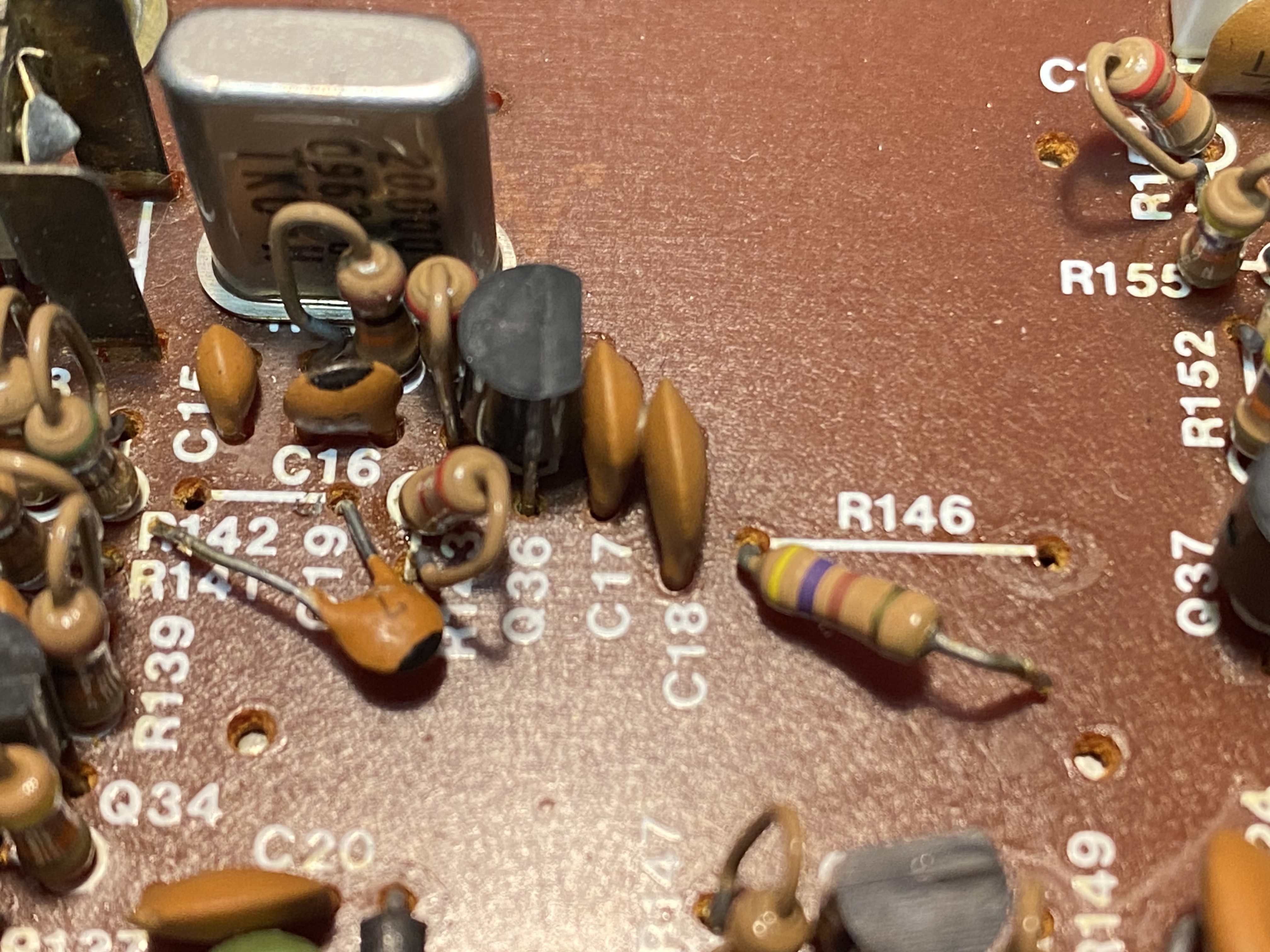
    The TS-930 was assumed to be installed SO-1, the 20 MHz TCXO with 12V operation. The manual indicates all of components should be removed before SO-1 insertion, but the current OCXO "unit" cannot be fitted to SO-1 foot print. So just,

    One terminal of R146 detached in order to cut off DC voltage source for the original crystal oscillator, and one terminal of C19 is detached to disconnect the output of the oscillator to the whole unit. If OCXO fails, just recover these two component as once is enough to be back to the original state.

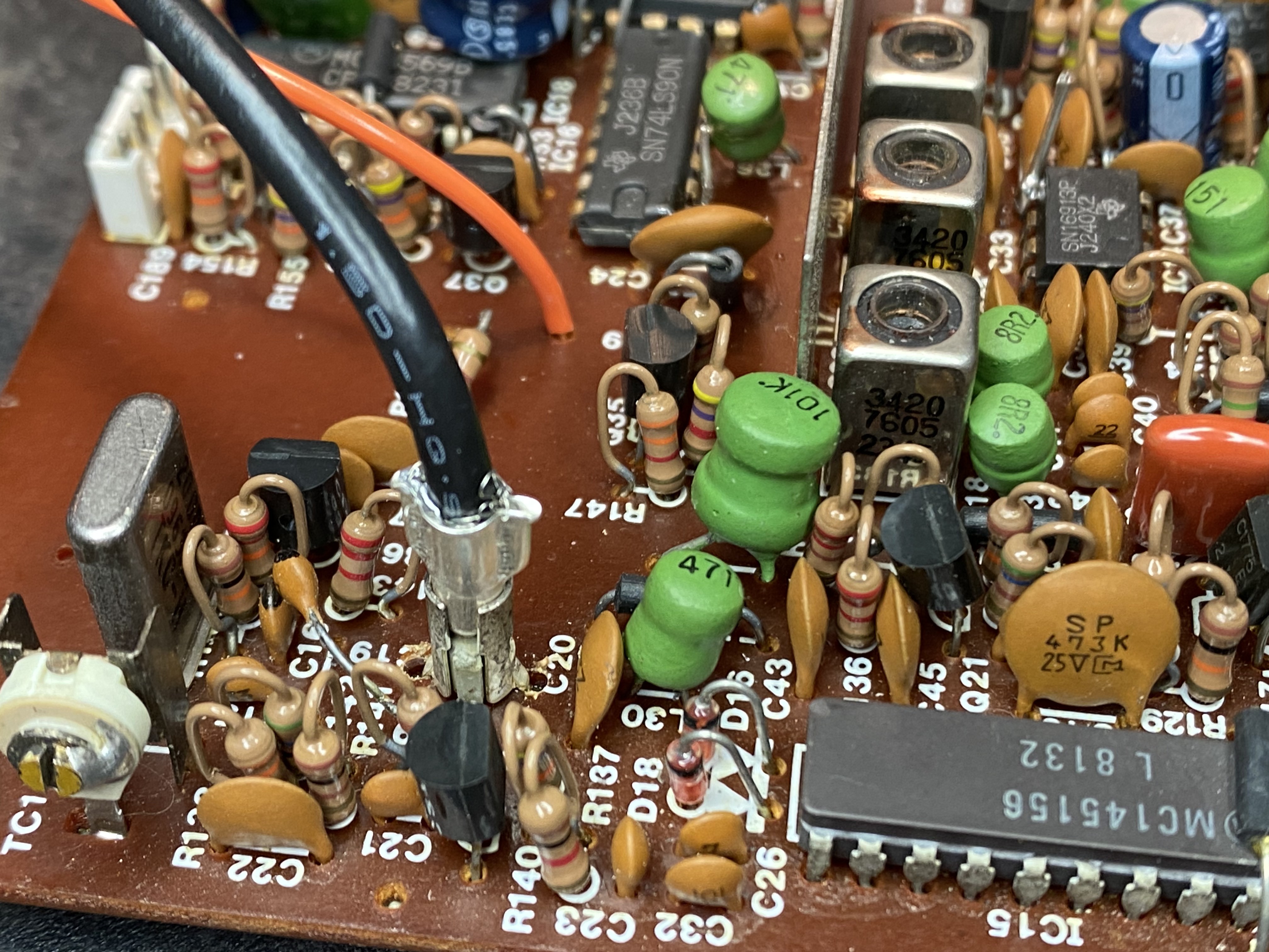
    Also the micro connector is added for the clock injection.

    So as a result, the signal from OCXO can be injected through this smart connector, and also it's very easy to recover to the original circuit.

View project log

Enjoy this project?

Share

Discussions

Similar Projects

Does this project spark your interest?

Become a member to follow this project and never miss any updates