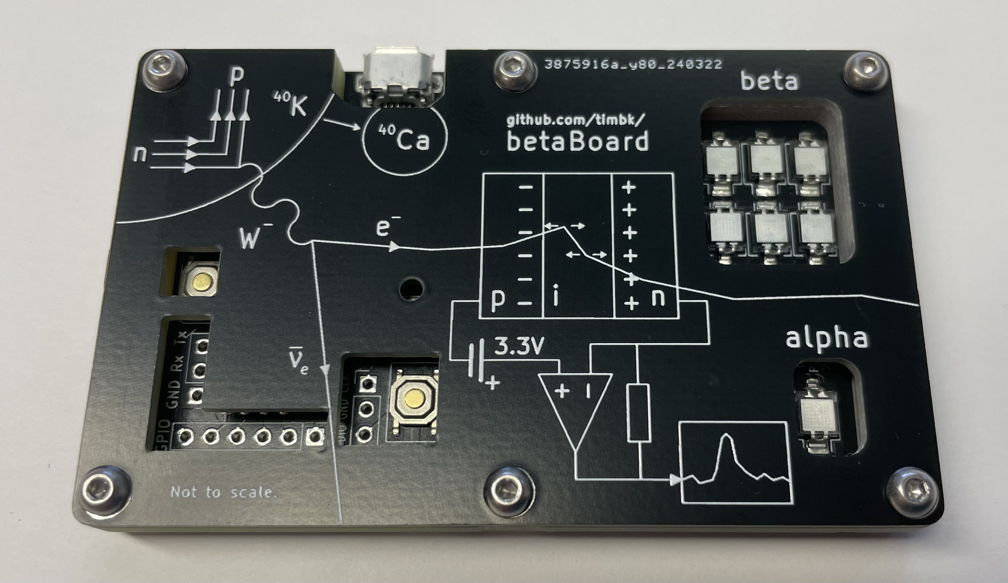
The detector principle is illustrated on the top of my second revision design:

A beta source like Potassium-40 (⁴⁰K) throws off very fast electrons (e⁻). These are the particles that we want to detect. Our detector is a PIN diode. The electron bumps into the atoms of our detector as it travels through it. With each bump the electron changes direction a bit and creates new charge carriers (electron hole pairs) in the sensitive volume in the middle of the detector. These charge carriers produce the current that we want to measure. My guess is that an average beta decay creates a pulse with a few hundred electrons as a signal. Luckily each charge carrier can also bump into other atoms and amplify the signal a bit.
PIN photodiodes are optimised to detect light particles (photons), but not the beta radiation that we are interested in. Especially with our limited voltage we can see that detecting the very small pulses will require a lot of amplification. This also means noise will be a concern. This is even more the case as we will run off a noisy USB supply.
If we assume that we have 1000 charge carriers induced within 100 us (1/10.000th of a second) this is equivalent to a peak current of 1.6 pA. Using an amplifier with an effective transimpedance of 2.2 GΩ these pulses become measurable at an amplitude of 3.5 mV.
To get a higher event rate, six diodes are connected in parallel. This way we increase the sensitive area and the detection rate by a factor of six.
Concept
The main difficulty in the design here is in the analog frontend. For the microcontroller I'm mostly just following the recommendations in the hardware design with RP2040 document. As we are just using built-in ADC of the RP2040 to digitise our signals, there is not much to do either. Using the integrated ADC reduces cost and complexity and allows for high sample rates without fiddling with external buses. But we will of course have to accept the infamously high non-linearity of the RP2040 ADC.

Input Amplifier design
Being powered through USB, this design is already quite limited. So we want to use a rail-to-rail operational amplifier here in order to not loose any more voltage headroom than necessary. There are many possible chips available. My choice was the MCP6232 as it checks all the boxes and is relatively cheap:
- Rail-to-rail operation
- Can be powered through 5V
- Low input bias current
- Decent power-supply ripple rejection
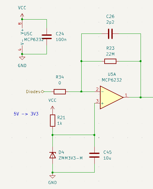
Our particle detector creates small current pulses. As these are difficult to work with, we will first use a transimpedance amplifier to convert this into a voltage signal. I started my design based on the DIY particle detector by Oliver Keller, but there are quite a few things I had to change to make it work with 5V. The maximum transimpedance (effectively the gain of the amplifier) possible is limited by the minimum bandwidth we require. With a small 2.2pF capacitor and 22 MΩ transimpedance we are already limited to 3 kHz.

Another major difference is that the USB power supply is significantly more noisy than the 9V battery in the design by Oliver Keller. Therefore the bias voltage on the positive input pin of the operational amplifier is implemented with a zener diode instead of a simple voltage divider. Also the capacitor C45 and resistor R21 act as a low pass to further stabilise the voltage.
Shaping Amplifier
The 22 MΩ transimpedance in the first amplifier are not enough to bring our signal into the range of our ADC. Another x100 amplification stage is required. This stage is also used to shape our signal, meaning that we will further cut the bandwidth of our signal, especially for low frequencies. By adding a high-pass filter we can get rid of most of the mains-frequency hum at 50 Hz (or 60 Hz respectively). By low-pass filtering to below a few kilohertz we get rid of most of the USB related noise.
Power Supply
Using a linear regulator would be a simple way to stabilise our power supply, but it would loose some of the voltage we already have. It would also add another expensive component. Therefore I have opted to just add an RC low-pass filter made of a 4.7 Ω resistor and a 100 uF capacitor. At the very low currents of that the analog portion of the circuit needs the small resistance drops significantly less than 1 A.
The full schematic can be found here.
 Tim - DJ8TK
Discussions
Become a Hackaday.io Member
Create an account to leave a comment. Already have an account? Log In.