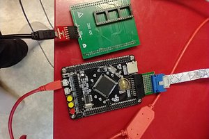
This is a custom RP2040 based business card that runs Ultrix/DECwindows. Please see the github repo for more details. From the README.md:
Software
PIO:
The PSRAM/HyperRAM PIO engine provides 42/32 MB/s (write/read) of memory bandwidth. Further, four PIO engines are used to provide four seperate read/write memory ports. This allows independent memory access for the emulated CPU, video DMA, and receive/send Ethernet traffic. Note that all 32 instruction slots are used.
The video PIO engine can support up to a sysclk/2 pixel rate. Thus, for the 300 MHz sysclk typically used, it is possible to run 1080p60 at a pixel rate of 148.5 MHz. The default video rate is 1024 x 768 @ 70Hz, as this matches the screen used for development and the pixel rate is an integral divisor from sysclk. Only five PIO instruction slots are used.
DMA:
To drive the video PIO engine, five DMA channels are used. They are allocated as follows:
- ctrl_dma_chan - points to DMA channel command packets
- data_dma_chan - executes DMA command packets
- ps_read_chan - points to PSRAM read data buffer
- inc_dma_chan - used to generate loop counter indices
- cur_inc_dma_chan - used as cursor loop counter
This project uses the RP2040 DMA sniffer to dynamically generate PSRAM addresses, which eliminates the need to have a per-line PSRAM command packet. Further, it uses the inc_dma_chan to enable DMA command loops, eliminating per-line DMA commands needed to send commands to the PIO pixel and PSRAM PIO engines. This makes the amount of memory needed to drive video independent of the display format. Currently, 86 DMA command packets are used vs. approximately 2250 required for 1080p if a per-line DMA structure was used.
In order to eliminate the latency from when the PSRAM PIO engine FIFO has read data, and its delivery to SRAM, we use the ps_read_chan. This channel is chained to after a PSRAM DMA command is executed. Without this channel, the PSRAM PIO engine FIFO would be not be emptied until the next DMA command is executed. This impacts the non-video PSRAM channels, as they must wait unitl the video PSRAM command is complete.
USB:
The USB HID code supports (at least) two keyboard/mouse combo types: Rii mini X1 (model: RT-MWK01), purchased at MicroCenter, and Logitech K830.
Emulator:
Dmitry's code at http://dmitry.gr/?r=05.Projects&proj=33.%20LinuxCard was modified to support the RP2040, as well as adding support for video and USB mouse/keyboard input. With overclocking and running the assembly language version of the CPU emulator, Dmitry's Linux image reports a BOGOMIPS rating of 13.44.
2.0) Getting started
2.1) Hardware
Build either rev 1.5 or 2.1, using the appropriate emu_brd directory. Please note that rev 2.1 is still undergoing Ethernet debug, and has exhibited significant packet drops. I use JLCPCB for board fabrication, and there are Digikey BOM spreadsheets in doc/bom. Recommend building two boards: one to use as a 1.8v CMSIS debugger, and the other as the target. Feel free to only populate the RP2040 related components on the CMSIS debugger.
The surface mount parts aren't too troublesome - I find the PSRAM BGA to be much easier to solder than the RP2040 QFN. My technique is to use a hot-air SMT rework tool. Recommended assembly steps:
- Solder the voltage regulator, check for 1.8v and 3.3v when done.
- Solder all of the passives, the RP2040, flash, and the USB connectors if building rev 2.1. (Note that two bodge wires are needed to connect J5 and J11 D+/D- as my assumption that USB-A could serve as non-host connector was incorrect). When done, use blink_bringup (below) to check connections. (Edit blink.c to enable the pins to check).
- Solder the HyperRAM chip, run mem_test to check connections.
- Solder the voltage translator chips, edit blink.c and run to check connections.
- Solder the connectors.
For rev 1.5: Needs modified waveshare LAN8722 board. In addition to the modifications outlined at: https://github.com/maximeborges/pico-rmii-ethernet...
Read more »
 Matthew Pearce

 Jacques Pelletier
 Antti Lukats
Super cool to see someone using my code! :D