 Jan Neumann
Open Echo - Open-Source SONAR
An ongoing open-source project is about building an open-source sonar for bathymetry and research.
Everything (code, schematics, board layout) is open source: https://github.com/Neumi/open_echo
I run a discord server, where we discuss progress: https://discord.com/invite/rerCyqAcrw
And I share progress on my YouTube channel: https://www.youtube.com/neumi
How the ECHO?!
An echo sounder is a device used to measure water depth by sending out a short burst of sound (usually in the ultrasonic range) and waiting for the echo to return. By measuring the time it takes for the echo to come back, the device calculates the depth of the water beneath the ultrasonic transducer.
Almost all boats use echo sounders for navigation and safety. Researchers rely on them for bathymetry, mapping, and archaeological studies. Search and rescue (SAR) teams use them for localization and recovery, while fishermen use them to locate fish-rich areas.
I needed an Arduino-compatible echo sounder for another project -a bathymetry GPS logging device. Arduino-readable echo sounders are hard to get, so I thought, why not build it myself? The basic working principle is simple, but the underlying electronics and physics are not always straightforward.
So, I took on the challenge and dove right in…
A running Arduino shield is public. Currently, I'm working on an all-in-one board with internal sampling, a microcontroller, a power supply, and the TUSS4470. Also a more advanced board for more exotic applications. Stay tuned!
Current state
- a running TUSS4470 Arduino shield
- a working python backend for real-time echo visualization in a waterfall chart
- reverse-engineered "LUCKY Fish Finder"
- read raw data from "LUCKY" receiver/amplifier to Arduino
- DIY transducer built and running
The custom Arduino shield uses a TUSS4470 ultrasonics driver from TI. It can be used to drive different transducer frequencies and is software-configurable. The Arduino ADC is used to sample the echo signal. The Python backend visualizes the return signal:
The TUSS4470 manages the driving and amplification part. It is configured by the Arduino via SPI and the drive frequency is generated on an Arduino pin. For 200kHz, signal generation is no problem. Higher frequencies and sampling sizes require a larger microcontroller in the future (solved in the all-in-one board with the STM32F103).
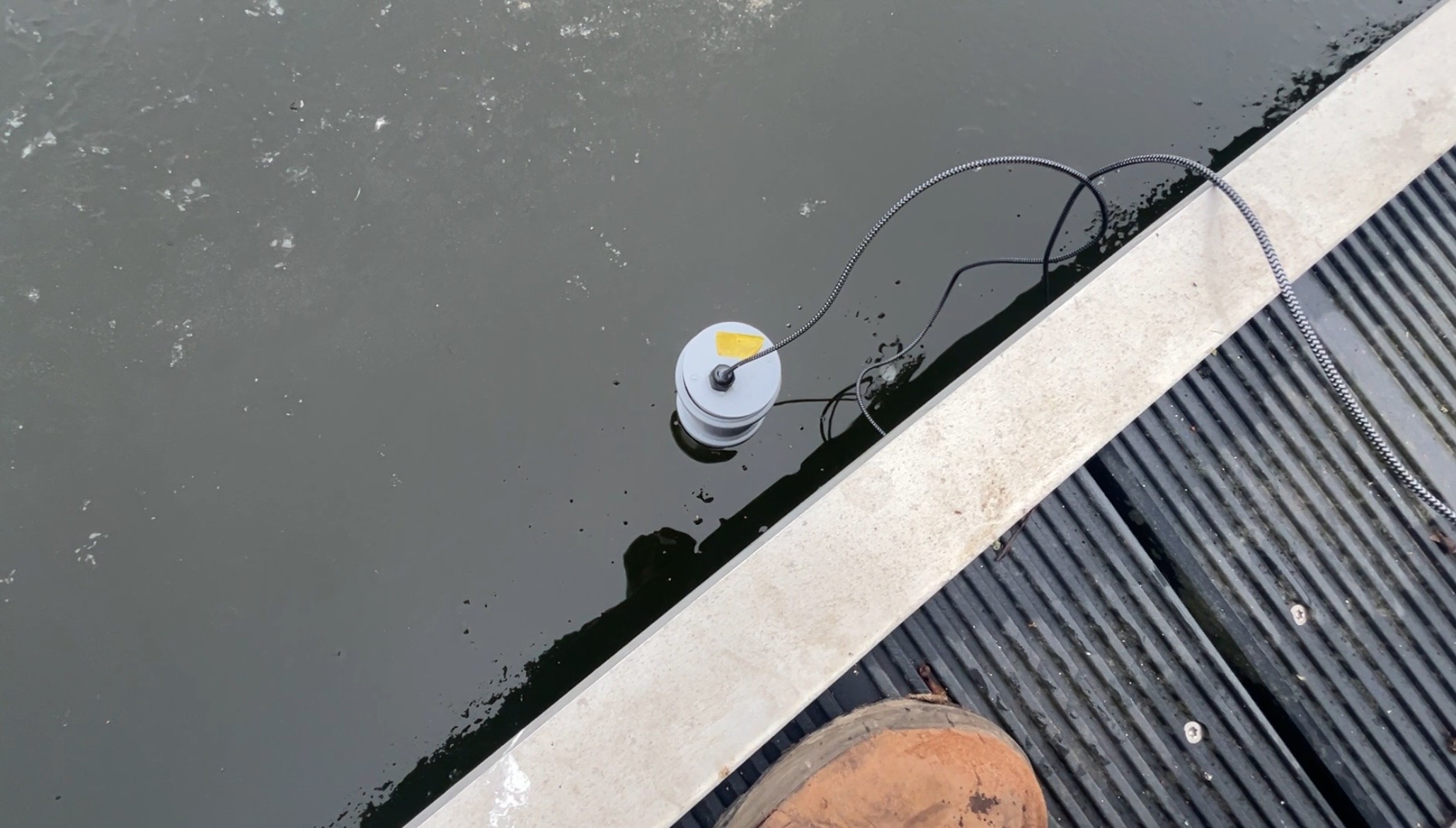
The TUSS4470 Arduino shield drives an external transformer to increase transducer voltage. The transducer is a cheap <10€ 200kHz 19mm PZT transducer from Aliexpress that is glued into a pipe cap with hot glue. The Arduino is connected via USB to the computer's backend. The TUSS4470 board is powered by three 9V block batteries in series to provide the TUSS4470 with a higher primary voltage. The transformer boosts this to about 250V p-p.
Usually, a high drive voltage and large transducer diameter is desirable to increase sound energy and receiver surface. But with large transducer sizes, capacitance, and ringdown time increase. The Aliexpress 200kHz is a good and cheap starting point.

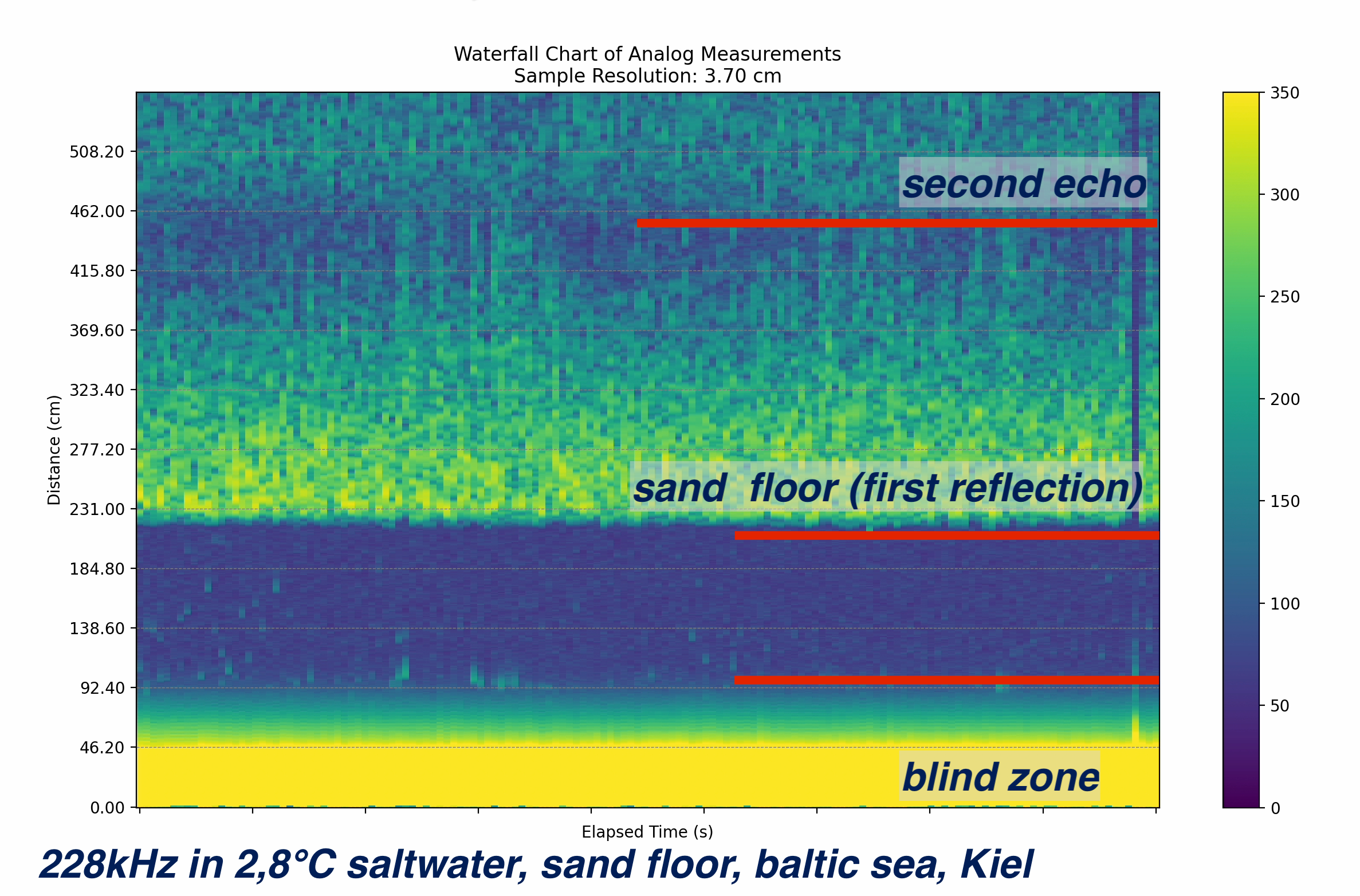
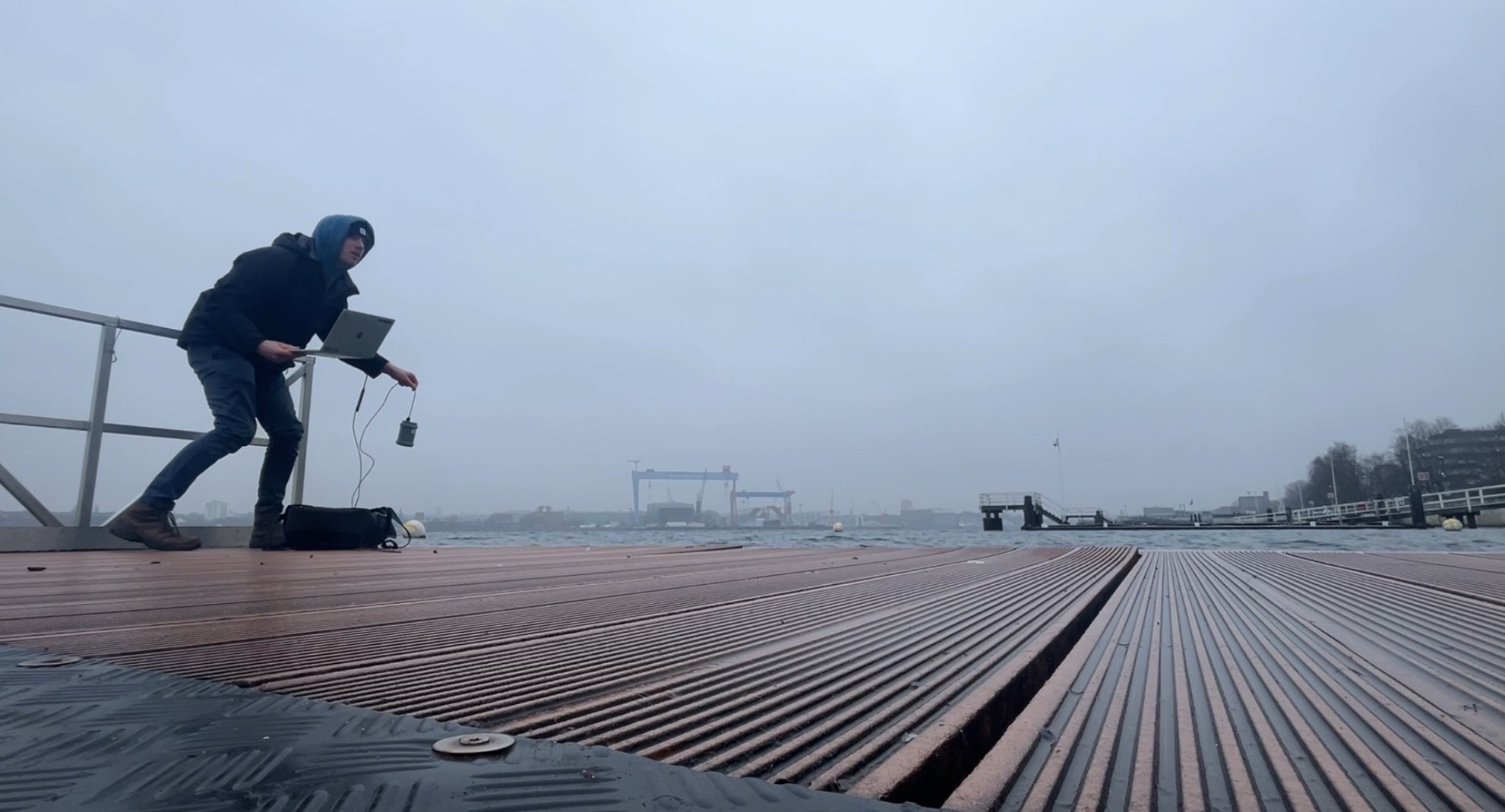
Testing the transducer assembly in the 2.8°C coooold baltic sea in Kiel, Germany :D
The 200kHz 19mm transducer penetrates a 20mm thick layer of ice and still gives OK results. It's important to have a layer of liquid water between the transducer's surface and the ice. The echoes are weaker than without ice between the transducer and water, but still, the ground is clearly visible, and even a second reflection.
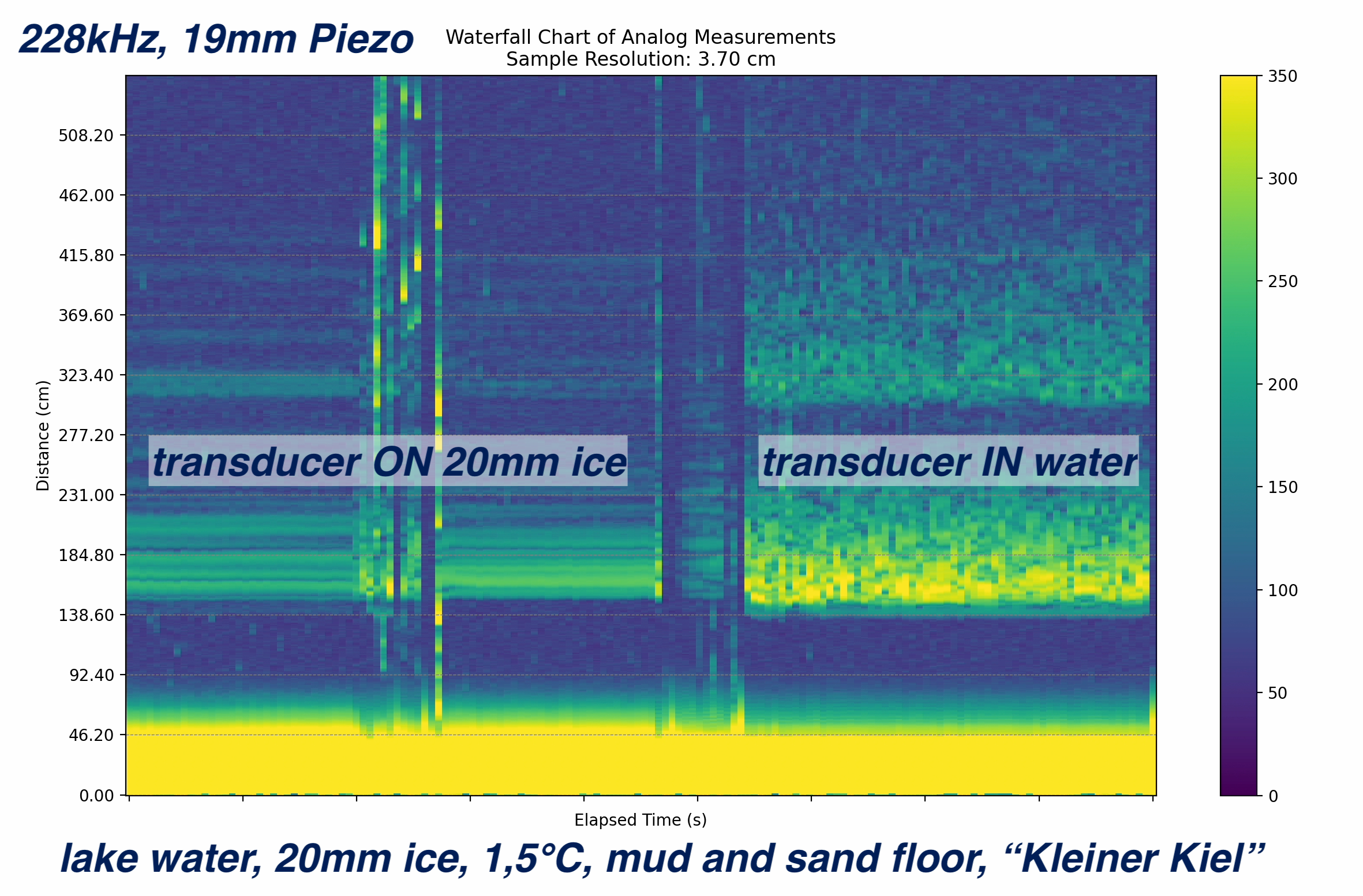
The waterfall chart gives you a better image of the past and allows better differentiation between a real echo and noise. Piezo transducers oscillate pretty long after the sound pulse has been sent. This is the lower yellow part in the plots (about 50cm). In this blind zone, you won't see echoes or reflections.
The range of the echo sounder not only depends on the electronics, but also highly on the transducer frequency and medium you use it in. For example, the above 200kHz setup has a range of only 50cm in air, but at least 8m in saltwater. This is due to the medium attenuation (which depends on the frequency) and beam shape (which is different in every medium). For a good starting point, 200kHz is good for underwater use.
As said, the beam shape highly depends on its frequency. A transducer with 10mm diameter and 100kHz will have a beam opening angle of about 130°, a 200kHz transducer of the same size about 55°. The higher the frequency, the narrower the beam will get. But attenuation also increases.
Also, the shorter the wavelength (higher frequency), the smaller the details you’ll be able to see. A 200kHz sound signal in saltwater has a wavelength of about 7.5 mm. The smallest resolvable object is approximately half the wavelength or about 3.75 mm.
A new board in the making
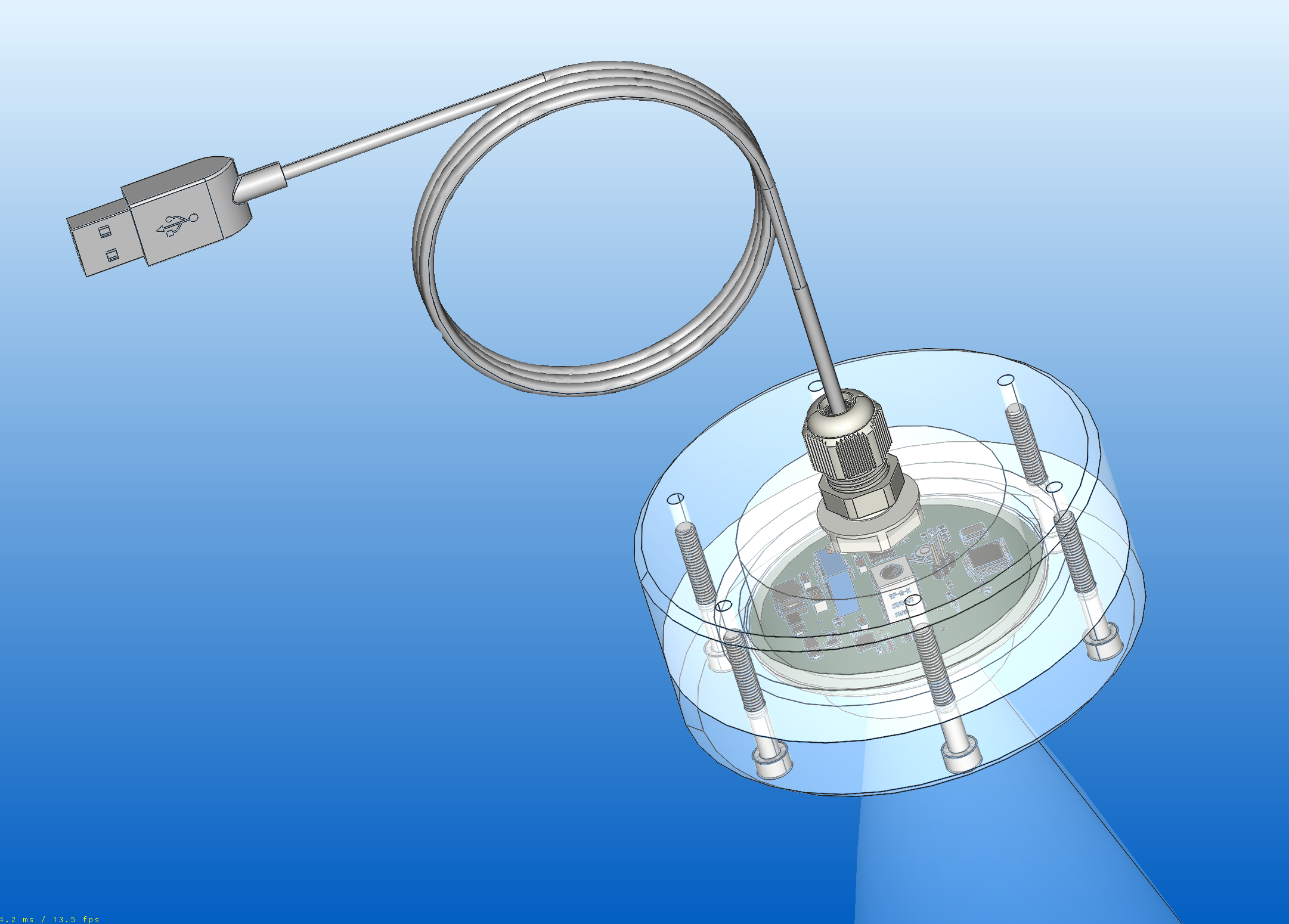
After the TUSS4470 Arduino shield, I’m now working on a new all-in-one board where all components are integrated into a single assembly. This unit can be encapsulated in epoxy, PU, or silicone for waterproofing and connects via USB to a computer with a Python-based backend and interface. This setup provides full software control over sampling, drive frequency, raw data, and more.
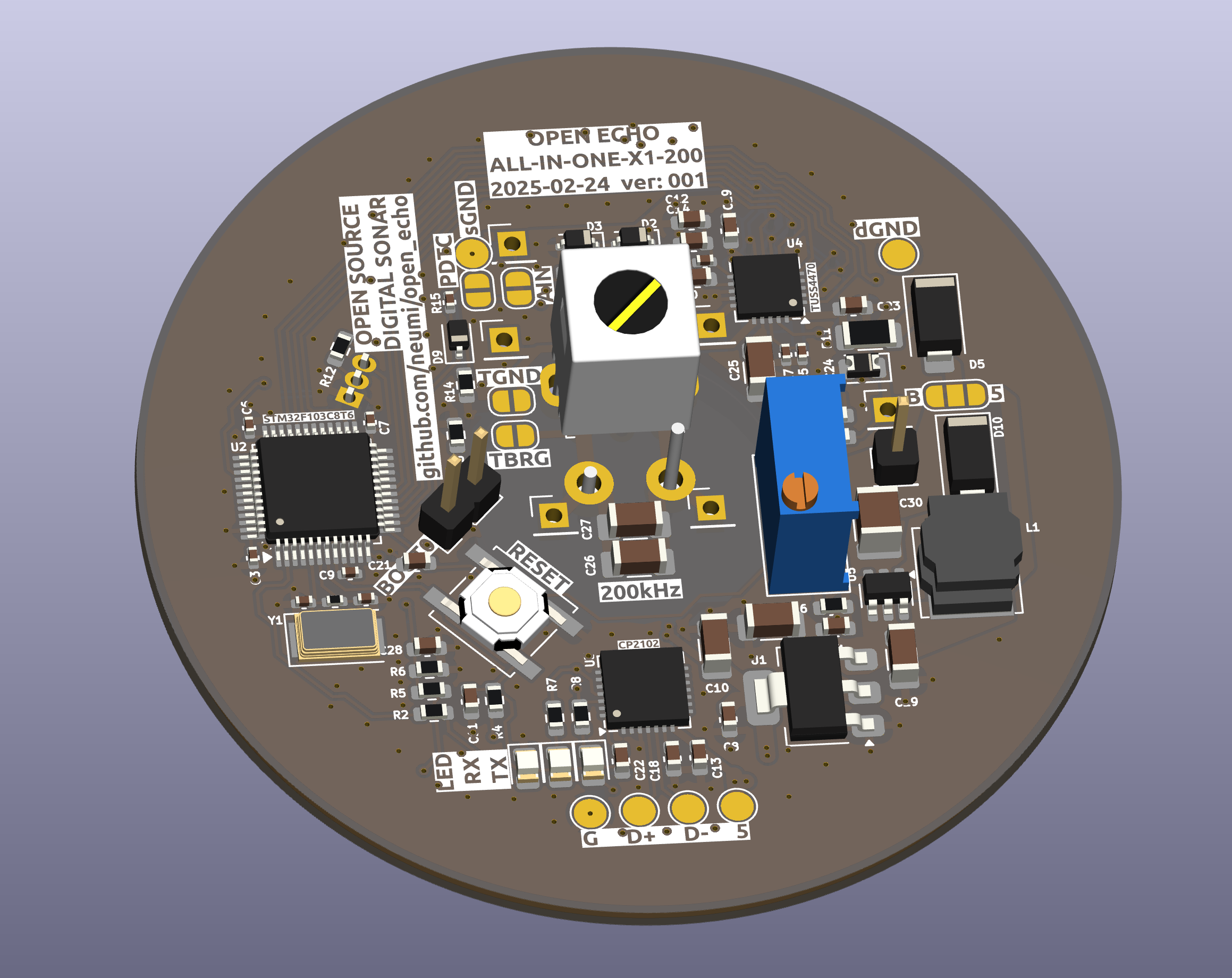
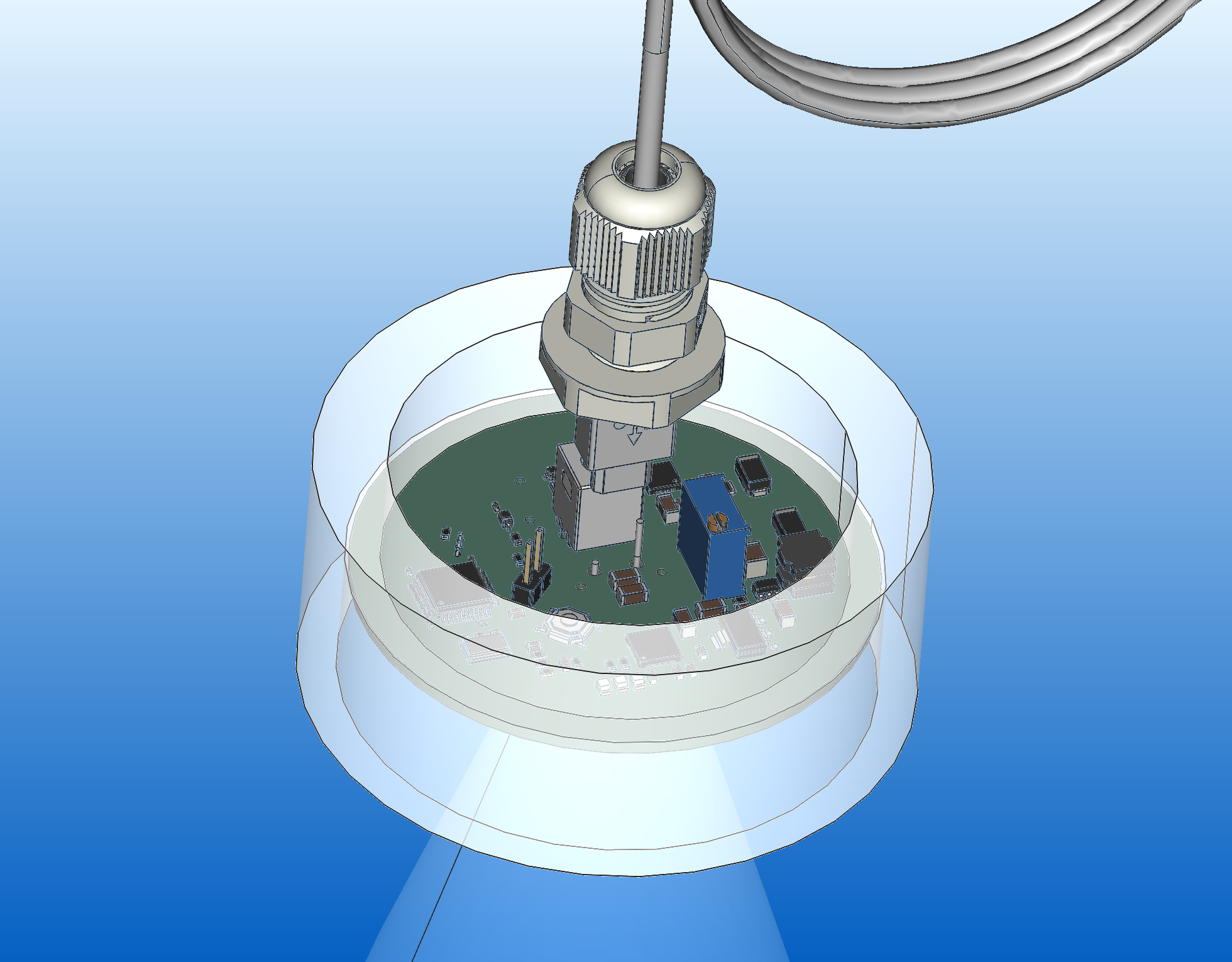
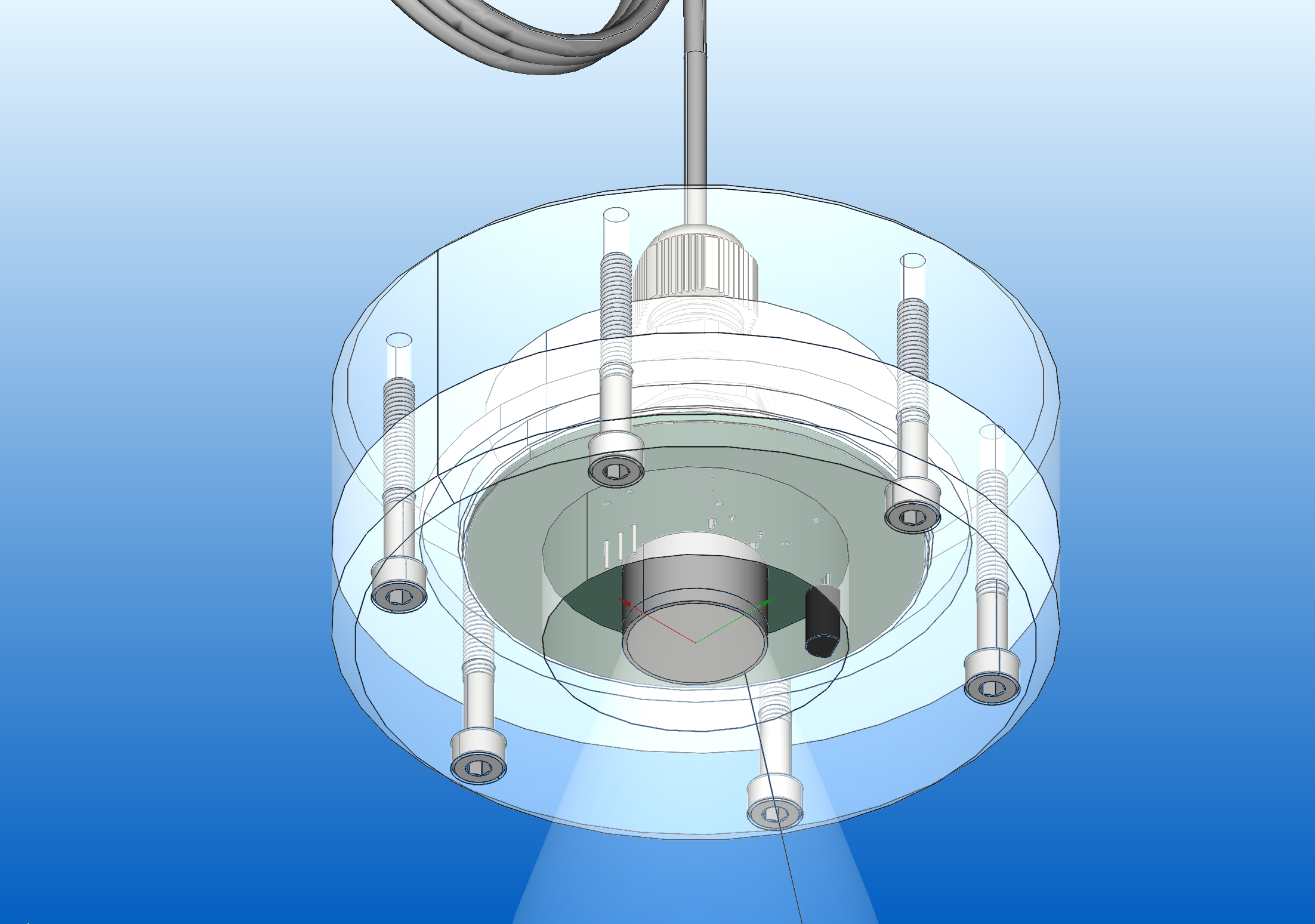
I just sent the ALL-IN-ONE PCBs to manufacturing (March 2025). The case will be CNC machined from aluminum or plastics and house the electronics to protect them from the environment. The 19mm 200kHz transducer will be PU or silicone encapsulated, while the active surface will directly contact the water.
All files will be online after the PCB has been tested and verified to work. (expected to happen in March/April 2025).
Underwater Dive Sonar
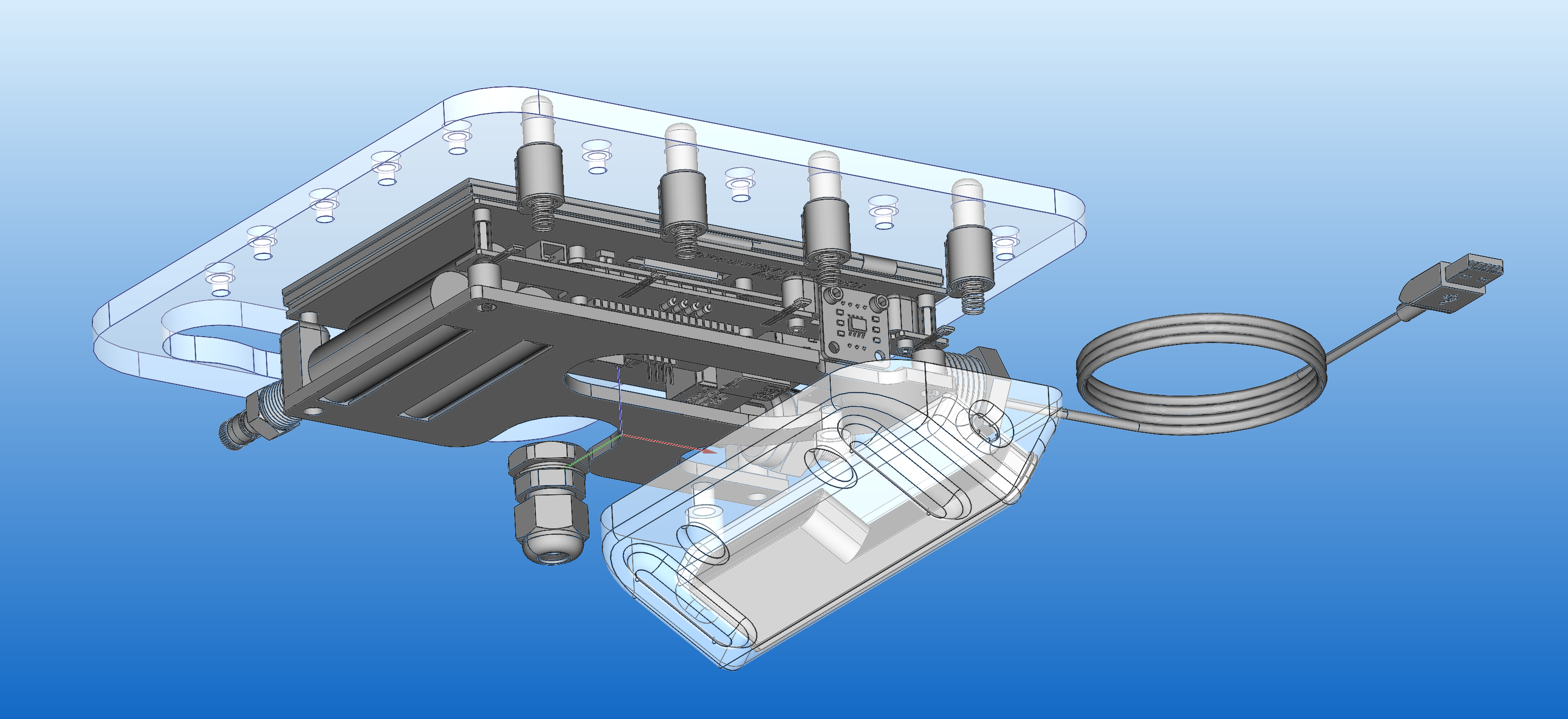
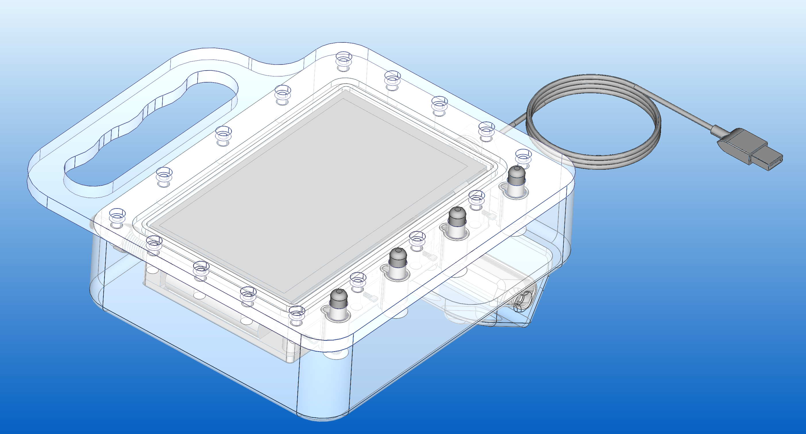
Besides the electronics design and RAW output Echo sounder, I'm also working on a dive computer with sonar. Based on a Raspberry Pi + 7" display, an IMU and the KOGGER Basic Sidescan. The first idea was to put the KOGGER Basic Side Scan Sonar on it. This will most likely be the easiest way of getting good underwater SONAR images. Maybe later, I'll build my own FAN sonar to put on the dive computer. But one thing after the other...
The FAN/Sidescan SONAR sensor, in combination with a gyro sensor, the Raspberry Pi, will show a sweep/scan of the forward-lying ground or obstacles like wrecks.
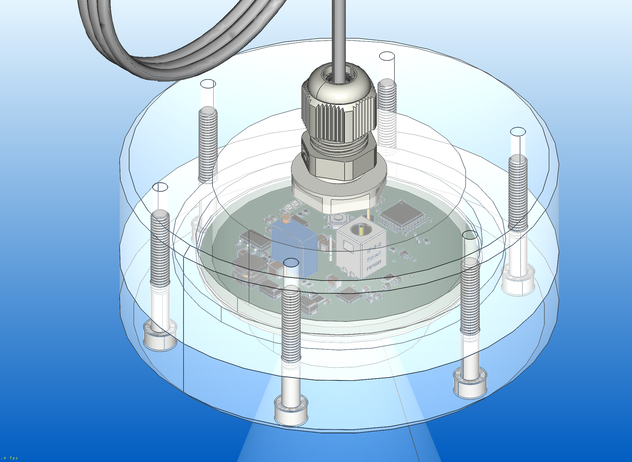
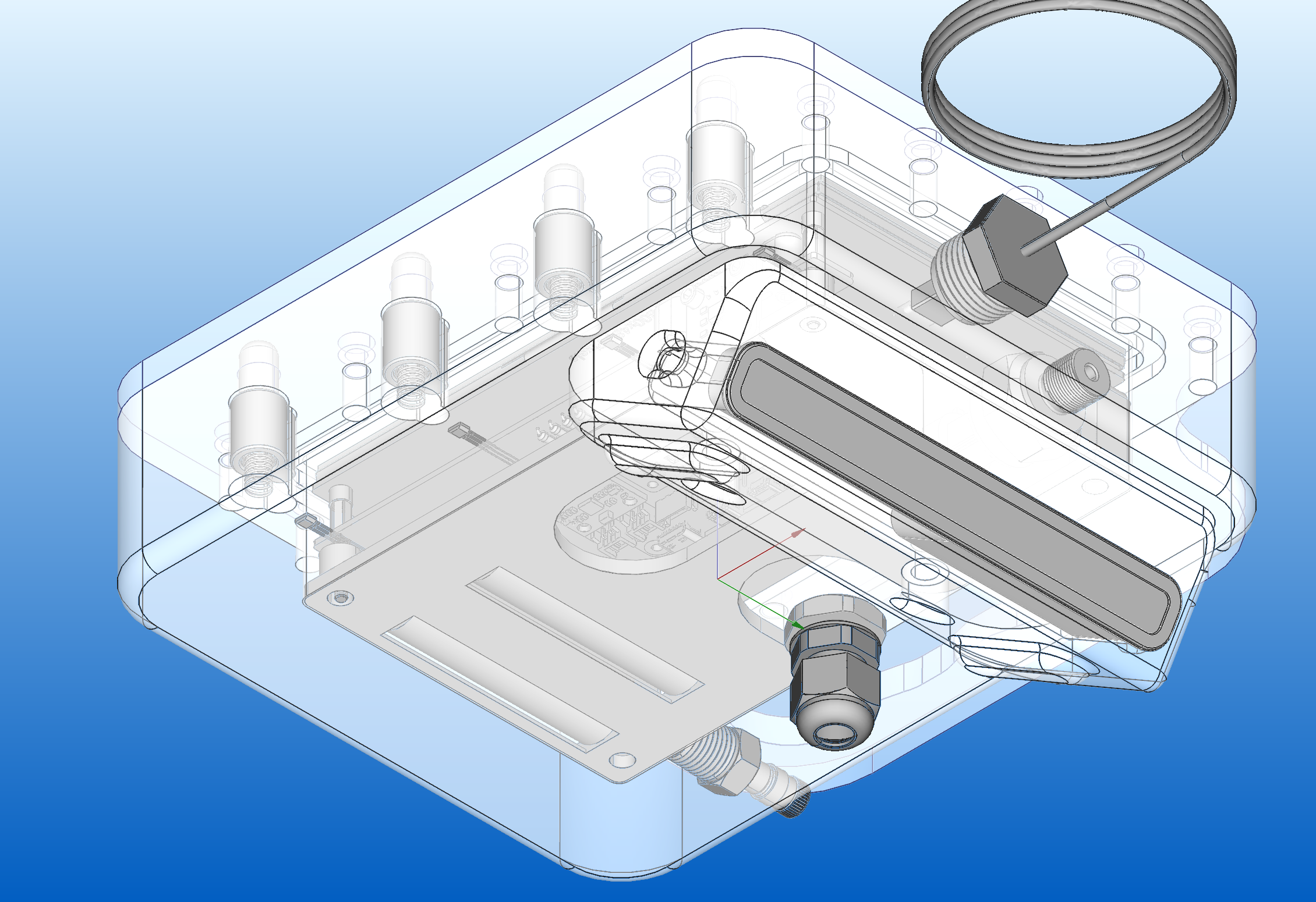
The case is machined from a massive 50mm block of PE. The lid is PMMA sealed with a 5mm O-Ring seal to the case. The inside is pressurized using dried air from a dive tank to prevent water from leaking in, preload the seals and to check for leaks (and to prevent condensation on the inside).
Four buttons with magnets interact with hall effect sensors on the inside on a carrier PCB on the RPi. The rest is for battery management, one magnetic rotary encoder, ADC for the pressure sensor, and a waterproof USB connector using a 1/2" water pipe cap.
I tested the KOGGER BASIC sidescan in the water a few times and the resolution and range is very very promising. (check the first video below) I have to do more testing, though, and write the software to use the gyro data to make it a sweeping sidescan sonar.
The first parts are already made... looking forward to higher water temperatures! (My 3D printer is broken currently, so the rest is on halt)
TO BE CONTINUED... Let me know what you think! I'm super happy when you have ideas to share!
Videos and updates
As soon as I have updates to show, I'll post on YouTube first...
I'm super happy to have KOGGER as a parts sponsor for this project!
Useful Links:
https://www.rapp-instruments.de/RemoteSensing/Roves/sidescan/sidescan.htm