powerfeatherdev
Motivation
Some time ago I had a cellular project that I wanted to do. It was going to be based on the ESP32 plus a NB-IoT/LTE-M modem. Furthermore, it was going to be deployed to a somewhat remote location, with no easy access to wall power. That meant having some sort of LiPo/Li-Ion battery and energy harvesting. Given the deployment location, solar was the best candidate.
I started looking at what modules in the market I can use to build my project. The most popular option seemed to be the Firebeetle 2. It had a couple of good things going for it:
- Low deep sleep current (less than 20 uA)
- Built-in LiPo/Li-Ion charging circuitry with an on-board TP4056
- Good value price-wise
However, it’s lacking in some areas:
- Max charging current is 600 mA
- Max recommended input voltage is only ~ 5 V
- No MPPT of some sort to more efficiently extract power from solar panel
I wanted to use a bigger battery to survive longer days without sun, especially since cellular is a little power hungry. And when the sun does come out, I wanted to charge as fast as possible so a higher max charging current was desirable. Some sort of max power point tracking or MPPT would also be very helpful in this regard. A higher max input voltage increases the solar panel options. Furthermore, I also wanted some other important power related features, if possible:
- Voltage and current monitoring for supply & battery
- Battery charge & health monitoring
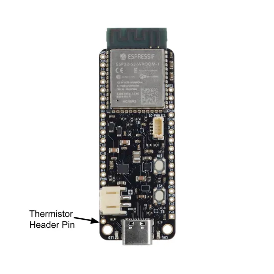
- Battery temperature sensing, temperature-based battery current control
- Enabling/disabling connected modules
Unfortunately, I couldn’t find a suitable module that has these features…and so I designed my own. Enter, ESP32-S3 PowerFeather.
Hardware
I designed the ESP32-S3 PowerFeather to be suitable for LiPo/Li-Ion and solar powered projects. It fulfilled the main requirements I had:
- Low deep sleep current (less than 20 uA as well)
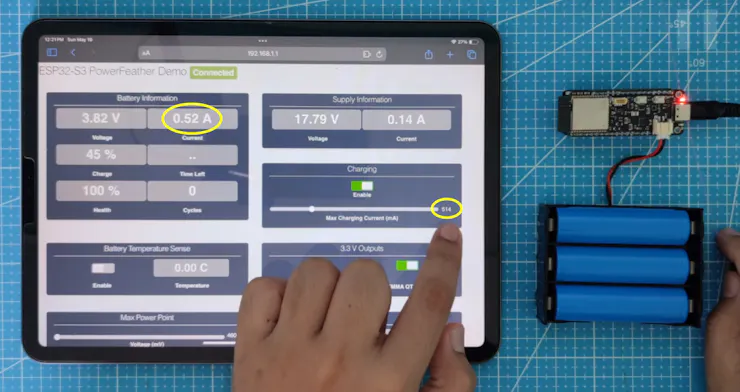
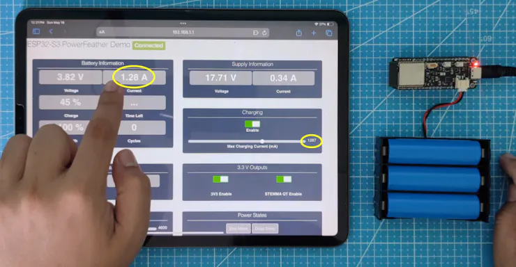
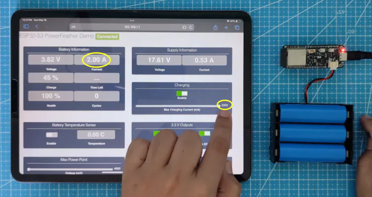
- Max charging current up to 2 A
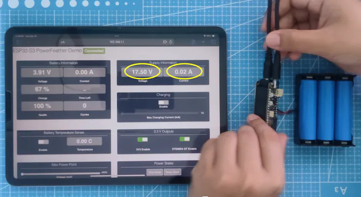
- Input voltage up to 18 V
- Not exactly MPPT, but a set maintained voltage can be set to prevent solar panel voltage from collapsing beyond the panel’s rated MPP voltage at near-MPPT performance
Plus, it had my ‘nice-to-have’ features and more:
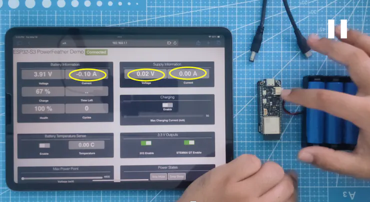
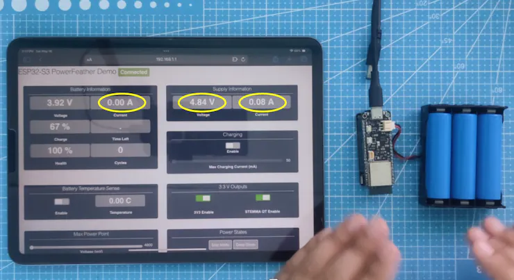
- Supply Monitoring
- Current measurement
- Voltage measurement
- Good supply detection
- Battery Monitoring
- Voltage measurement
- Temperature measurement
- Current measurement (charge/discharge)
- Charge estimation
- Health & cycle count estimation
- Time-to-empty and time-to-full estimation
- Low charge, high/low voltage alarm
- Battery Management
- Enable/disable charging
- Set max charging current
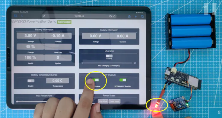
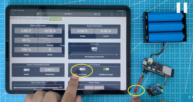
- Others
- 3V3 enable/disable
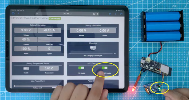
- VSQT enable/disable
- FeatherWing enable/disable via EN pin
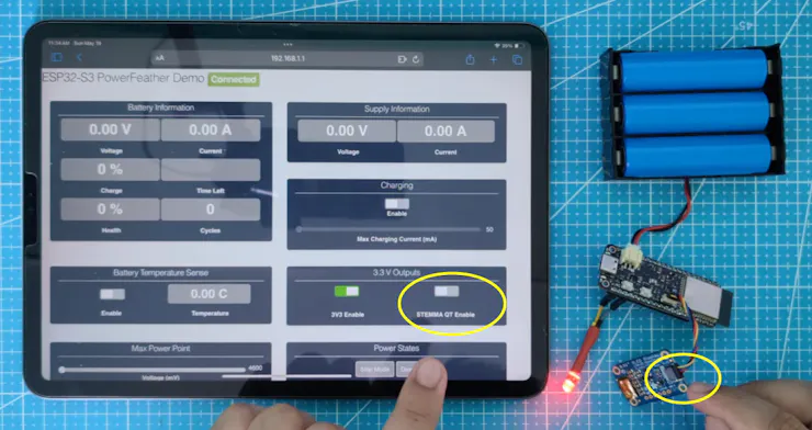
- Power States
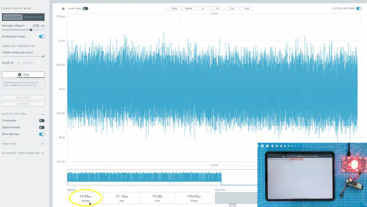
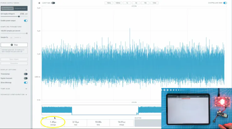
- Ship mode (< 2 uA)
- Shutdown mode (< 2 uA)
- Power cycle
- Battery Protections
- Undervoltage Detect @2.2 V, Release @2.4 V
- Overvoltage Detect @4.37 V, Release @4.28 V
- Overcurrent protection @3A
- Trickle charging safety timer @1 hr
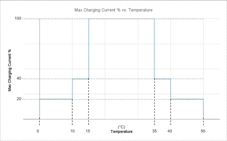
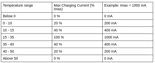
- Temperature-based charging current reduction based on JEITA, cutoff at 0 °C and 50 °C.
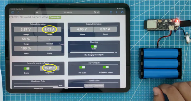
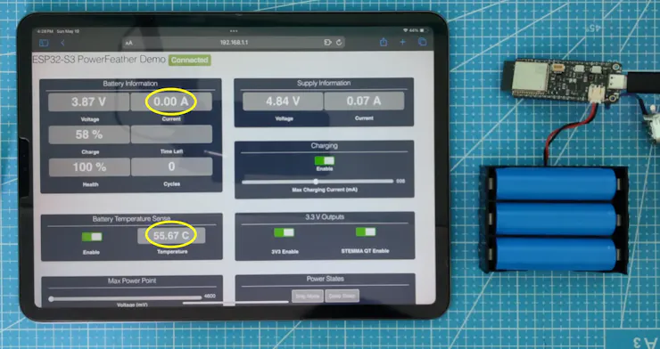
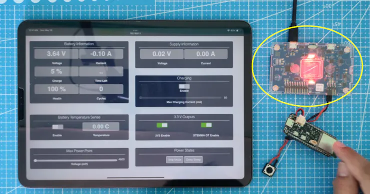
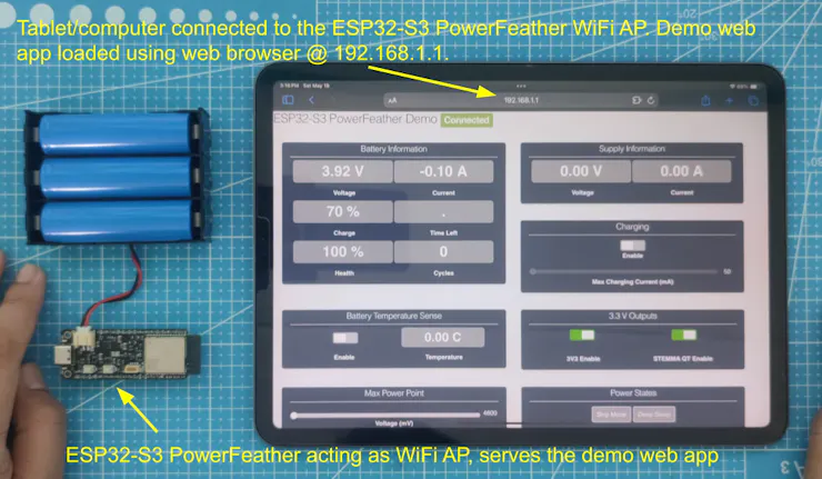
The monitoring features are especially useful in remotely deployed nodes to keep track if something is wrong and if an action needs to be done. To see how the power features of the ESP32-S3 PowerFeather compare to the FireBeetle 2 I mentioned above (and some additional hardware), take a look at this spreadsheet.
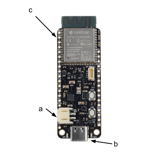
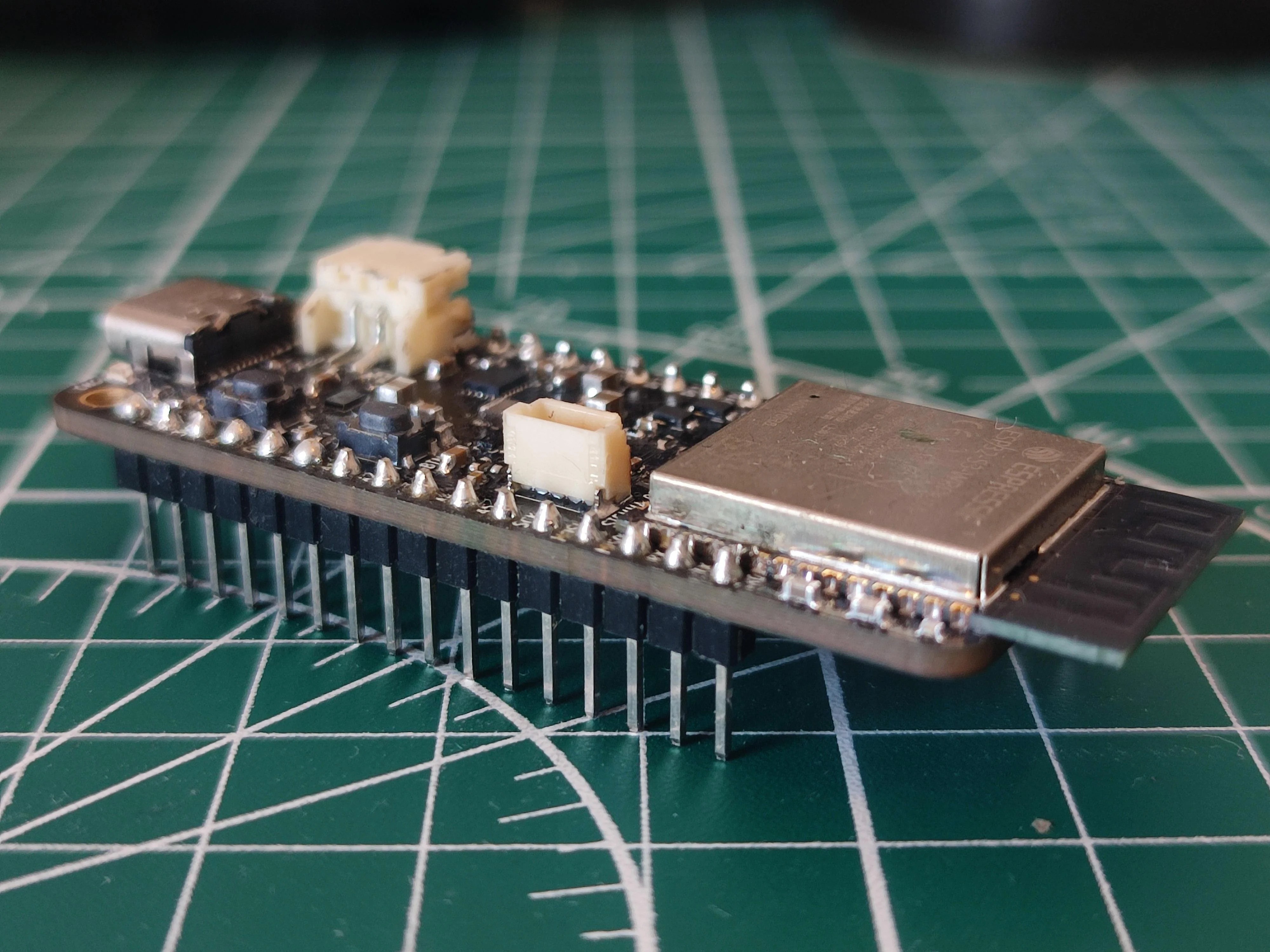
The extensive power management and monitoring features of the PowerFeather is mainly thanks to the on-board Texas Instruments BQ25628E battery charger IC and Onsemi LC709204F battery fuel gauge. Here is an overview of the important power-related parts of the board:

Software & Documentation
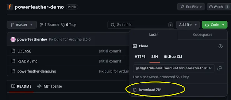
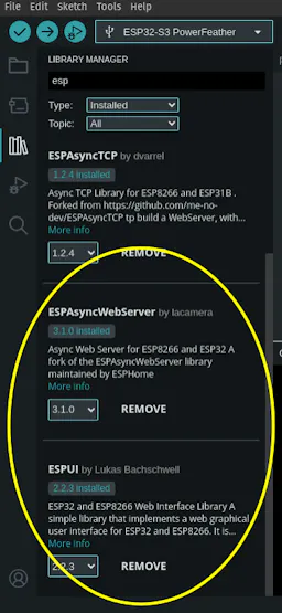
The TI BQ25628E and Onsemi LC709204F can be controlled using their I2C interface, which can get a little complicated. And so, I’ve also made available a helper library called PowerFeather-SDK to help users make use of the features of these chips, and the other power control and monitoring features of the board, more easily.
The PowerFeather-SDK is available on the Arduino Library Registry, as well as the ESP-IDF component registry. It’s...
Read more »