Why
I was googling for a while how to do programming of this variant, and this setup seems to work. I used Platformio for the first time and it was really good experience. Zero hassle, and it just worked. On top of that, i got to use my preferred editor rather than the Arduino IDE.
Requred hardware setup:
- ESP-12E (mine says AI-Thinker)
- USB-serial adapter (mine is SILABS 2102)
- Breadboard and some wires
- Power supply of 3.3V (mine was shipped with the breadboard)
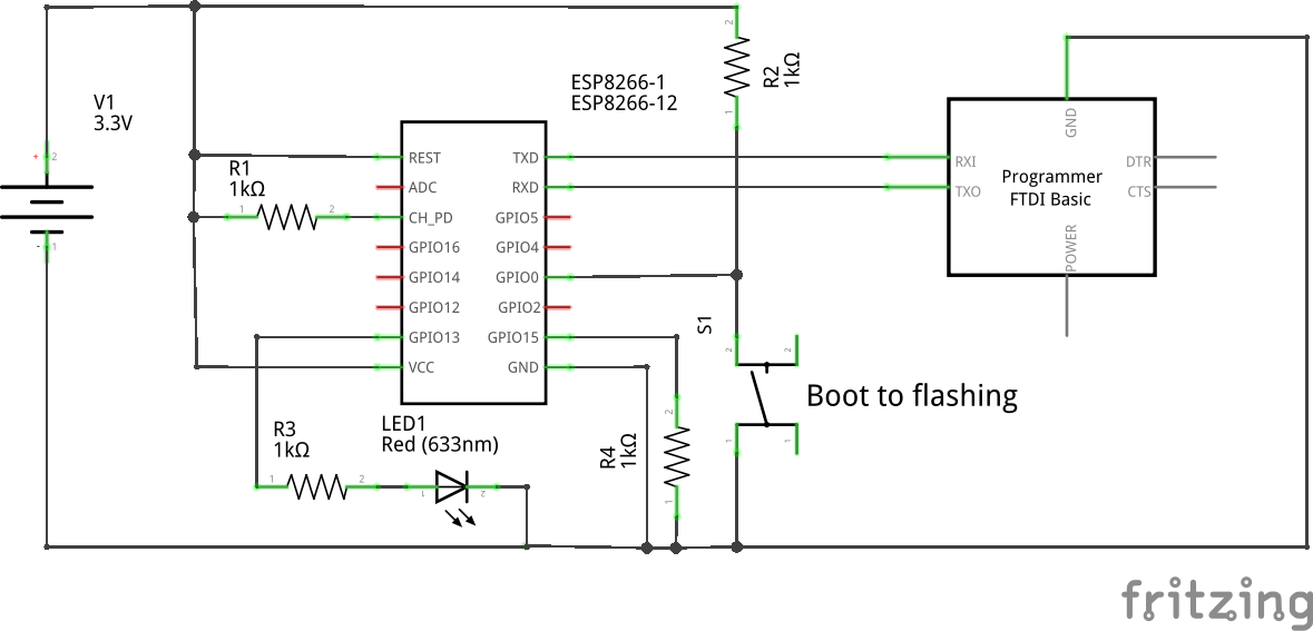
Image 1: Schema of the wiring. I used jump wires and it worked out just fine.

Required software setup:
I have ubuntu 16.04 running, but probably other similar distributions work fine as well.
- Install python-pip python-virtualenv cutecom
- Create new virtuaenv and install platformio inside it
- virtualenv ./ENV
- source ./ENV/bin/activate
- pip install platformio
Now the enviroment is set up, continue to creating the project and compiling:
- Create folder for the project and initialize it:
- platformio init --board esp12e
- Create sourcefile "src/main.cpp" with content below and compile
- platformio run
/**
* Test ESP8266 wifi and programming. Will print wifi networks to serial and blink led on pin 13.
 */

#include "Arduino.h"
#include "ESP8266WiFi.h"

#ifndef LED_BUILTIN
#define LED_BUILTIN 13
#endif

void setup()
{
  // initialize LED digital pin as an output.
  pinMode(LED_BUILTIN, OUTPUT);
  Serial.begin(115200);

  WiFi.mode(WIFI_STA);
  WiFi.disconnect();
  delay(100);
  Serial.println("Setup done");
}


void do_blinking()
{
  // turn the LED on (HIGH is the voltage level)
  bool state = 0;

  static const int LOCAL_DELAYS[] = { 200,400,200, 1000 };
  for ( int dloop = 0; dloop < sizeof(LOCAL_DELAYS)/sizeof(int); dloop ++ )
  {
     state = !state;
     digitalWrite(LED_BUILTIN, state);
     // wait for a second
     delay( LOCAL_DELAYS[dloop] );
  }
}


void scan_networks()
{
  Serial.println("Scan start");
  // WiFi.scanNetworks will return the number of networks found
  int n = WiFi.scanNetworks();
  Serial.println("Scan done");

  if (n == 0)
  {
    Serial.println("no networks found");
  }
  else
  {
    Serial.print(n);
    Serial.println(" networks found");
    for (int i = 0; i < n; ++i)
    {
      // Print SSID and RSSI for each network found
      Serial.print(i + 1);
      Serial.print(": ");
      Serial.print(WiFi.SSID(i));
      Serial.print(" (");
      Serial.print(WiFi.RSSI(i));
      Serial.print(")");
      Serial.println((WiFi.encryptionType(i) == ENC_TYPE_NONE)?" ":"*");
      delay(10);
    }
  }
  Serial.println("");
}
void loop()
{

  do_blinking();
  scan_networks();

}
Now we have binary ready, lets open terminal and observe how it goes:
- Power down ESP8266
- Prepare shell to run program, but do not run it yet:
- platformio run --target upload
- Power up ESP8266 and press the button to boot the ESP to programming mode
- Run the command above - after programming succeeds, power down the board.
Now we are all set, power up the board and see the serial line for the wifi network listing:
- Open cutecom, settings are 115200-8-N-1 - port is /dev/ttyUSB0
- Power up the board, no button pressed
- Observe blinking
Resources:
 Pauli Salmenrinne


 Ai-Thinker
 Rodmg
Rodmg
 cafelizardo
While doing some experiments with the ESP module some time ago we noticed, that it produces a quite powerful clock signal of 26MHz at GPIO0 while in bootloader mode. We could not find much references for this behavior but decided to add series resistors (330 Ohm to 1k) in between our button and GPIO0 and between our logic control (DTR of CP2101) and GPIO0 to protect the IO buffer of the pin.
We even rectified this signal and used it to detect if the device (Magic Shifter 3000) entered bootloader mode accidentally.