 Jesse Farrell
I originally had aspirations to make this a nicely polished project, but I'm a little too busy to make this a fully fleshed out design before the summer heat really hits. The core of this design is a latching solenoid, and a water gauge. A latching solenoid was critical since this widget will be running off batteries. It allows you to toggle the state of the solenoid by sending a short 5V pulse, once the state has changed the device can be unpowered and it'll hold wherever it was left.
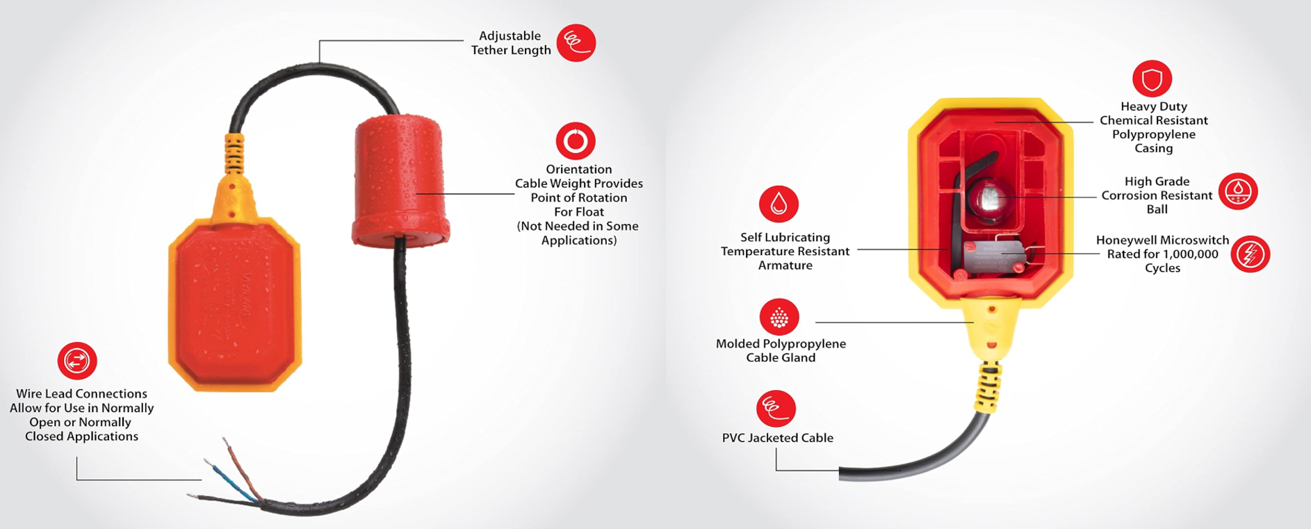
The water gauge, or float switch, is pretty simple; its a buoyant cavity on the end of a wire. Inside the cavity is a heavy ball bearing that opens/closes a switch based on the orientation of the cavity. When the water rises, the object floats up allowing the ball bearing to roll to the opposite side of the cavity.
All that I'm missing is a cheap micro to control everything. Luckily, I have an ATTINY1616 on hand so I'll use that... to be honest, it would be a fun project to replace this entire design with 74 series logic, but given my time crunch I went the "keep it simple stupid" route.
H-Bridge!!!
Who'd of guessed.... I need an H-bridge. My supply of P-channel mosfets is VERY low, so I'll have to get by with BJT's instead. It's not ideal, but given the solenoids relatively low power requirements I should be fine (5V @500mA for 30ms). I had to dig fairly deep for a good npn/pnp pair, but I finally found the SS8050/SS8550. They can handle the current, but I’m a little concerned by their Vbe rating… I’ll definitely need to scrap together a breadboarded prototype. Here's the somewhat finalized circuit.
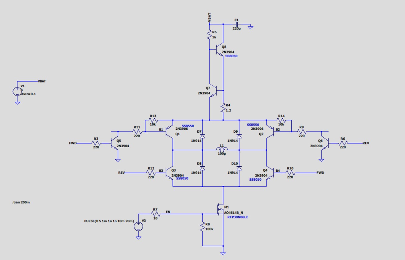
I’m running it off an unregulated 9V battery, so care to be taken. I added a current limiting circuit (Q7/Q8), to better maintain the 500mA load across the batteries discharge curve.
Since I’m worried about power consumption, I added a low side switch that completely disconnects the circuit when its not in use (I might remove this later, depending on how tests look). The hope being it would stop any leakage through this circuit, but I’m suspicious it may do more harm then good.
Lastly, I flipped the polarity on my upper transistors using NPN’s. I wouldn’t be able to drive the PNP’s since my MCU can only output 3V3. The emitter of Q1/Q2 will be somewhere b/w 9V to 5V, so I’d never be able to turn either one off. This has the added benefit of nicely matching the 4x bases of my H-Bridge. Q1 and Q4 can now have their control signals tied together (thanks to Q5’s inversion), and same goes for Q2 and Q3.
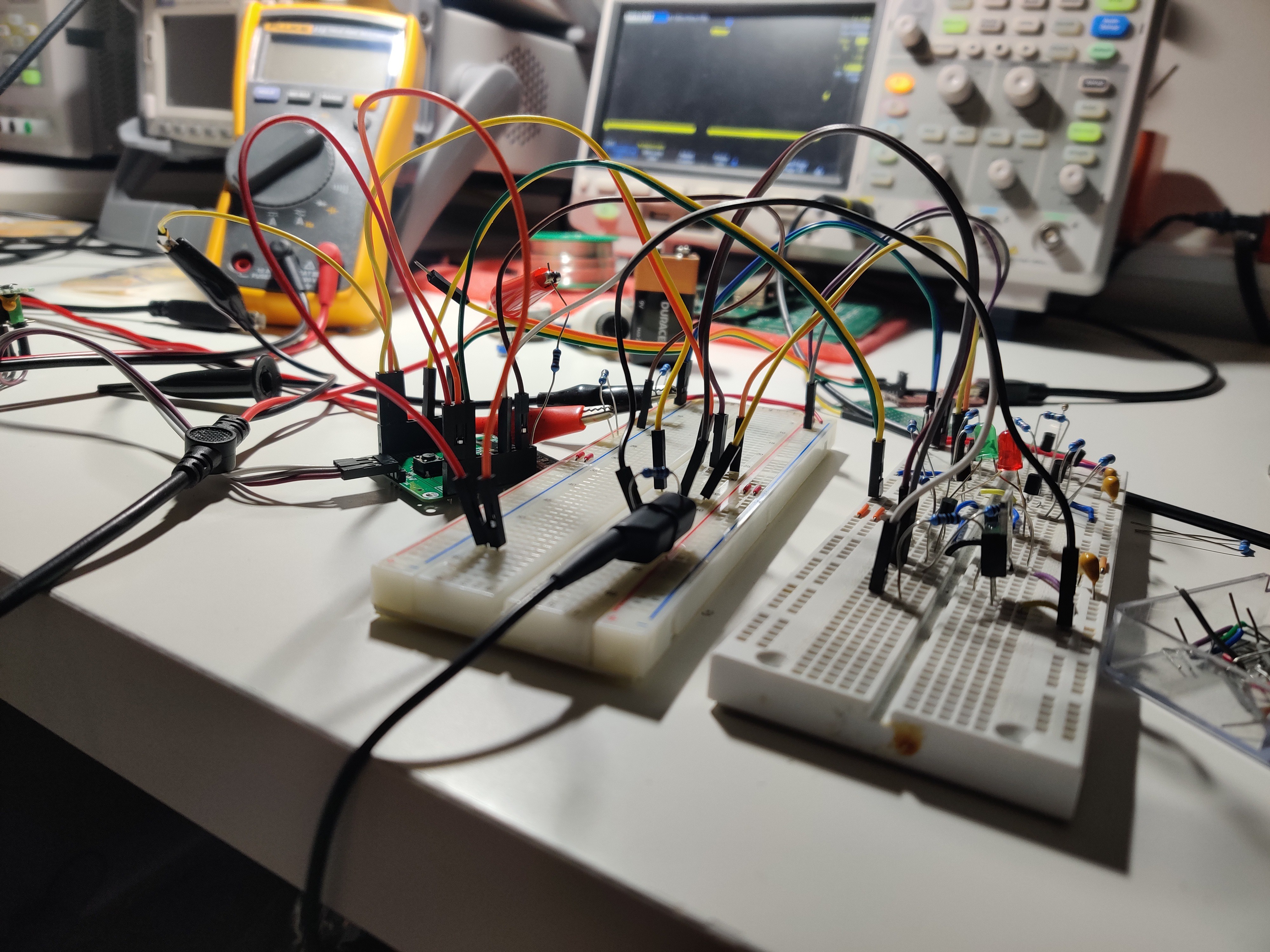
Current Limiter Test
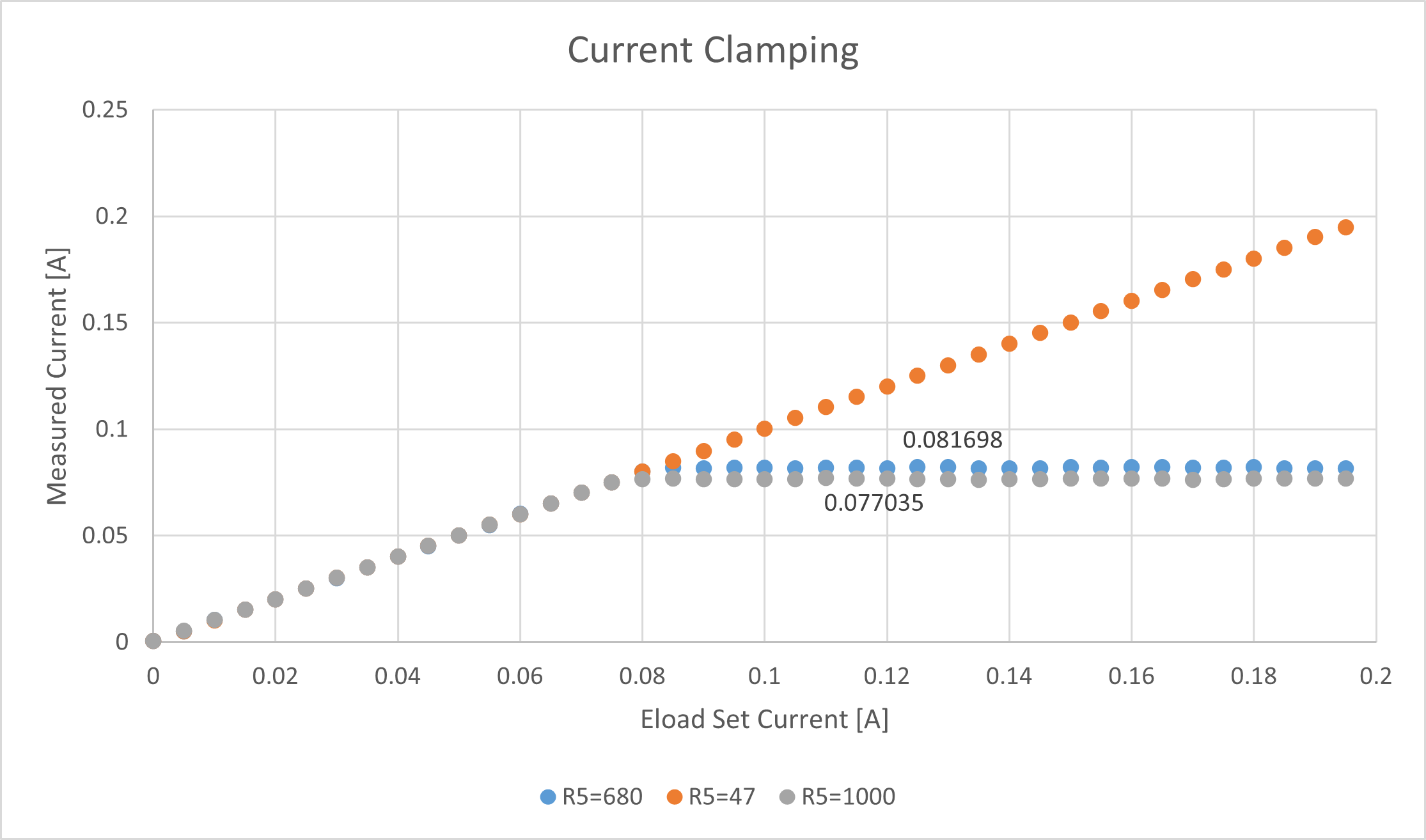
A quick breadboard test of the current limiter. I connected “VBAT” to a PSU at 9.5V, and connected the output of the current limiter to an ELOAD. At this point I wasn’t sure if I wanted R5 to be on the smaller side, so I tested a couple values shown below. I expected ~70mA current limit, and that’s more or less what I saw. I’d like to do a quick sanity at temperature before I deploy the widget… I know Vbe can vary with temperature, but I forget with what sort of magnitude. (TODO - Investigate)
The automation only took a view lines of code thanks to an SCPI library I’ve been working on. If you haven’t poked PyVISA yet, I’d HIGHLY recommend it!
#Overview:
# Testing the current limiting of my BJT circuit - July2024

from DriversPy.ELoad import *
USER_Eload_ip = "192.168.1.13"

eload = ELoad(USER_Eload_ip, DBG_Print = False)
eload.LOAD_OFF()

# VARS
CR_Values = list(range(0,200,5))
CR_Values  = [x / 1000 for x in CR_Values ]

# Test CC
eload.SET_MODE(LoadType.CC)
eload.SET_CR_VAL(10000)
eload.LOAD_ON()


for R_VAL in CR_Values:
    sleep(1)
    eload.SET_CC_VAL(R_VAL)
    sleep(0.5)
    I = eload.GET_Current()
    V = eload.GET_Voltage()
    print(str(R_VAL) + " " + str(I)+" " + str(V))

eload.LOAD_OFF()
End Of Day 1
By the end of day 1 I have all my HW solidified, but there's still some FW that needs to get done, and some bugs that need squashing. The last thing I found today was flakiness reading ADC values from my ATTINY1616. Likely just some register configs I'm missing.Next Steps (1) Rough Power Analysis, (2) Finalize Code, (2) Perf Board It!
.
.
.
Discussions
Become a Hackaday.io Member
Create an account to leave a comment. Already have an account? Log In.