 Jesse Farrell
With Christmas PTO fast approaching I thought I’d focus on finishing up some projects. My goal is to order PCBA to tinker with over the holidays.
A quick overview of the “WellWatch” project. This widget essentially just monitors a float switch/gauge and toggles a solenoid accordingly (see the project homepage for why I’m doing this). Some challenges that make this project a bit more interesting is (1) the system will be operating from a Solar cell, and (2) it will support a variety of switching voltages.
The core blocks of the system are shown below and include Power (PWR), Microcontroller (MCU), Pulse storage, and H-bridge.
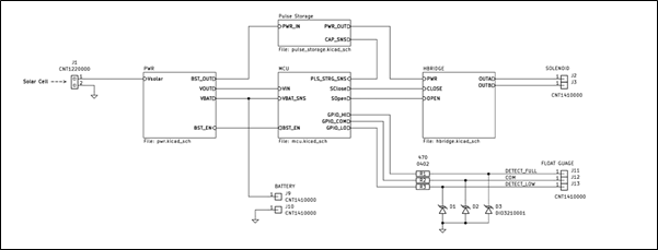
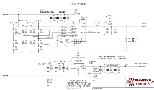
PWR – Harvests energy from solar cell and stores that energy in a single 400mAh LIPO cell. Battery voltage is exposed on VBAT, and a regulated version of VBAT is exposed on VOUT. When BST_EN is asserted, BST_OUT generates between 5 – 24V depending on the hardware configuration.
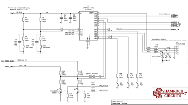
MCU - The microcontroller block contains an ATTINY1616 which; controls the H-bridge circuit via SOpen and SClose (solenoid open/close), senses the state of the float switch via GPIO_HI, GPIO _COM, and GPIO _LO, and measures VBAT as well as the pulse energy storage capacitors.
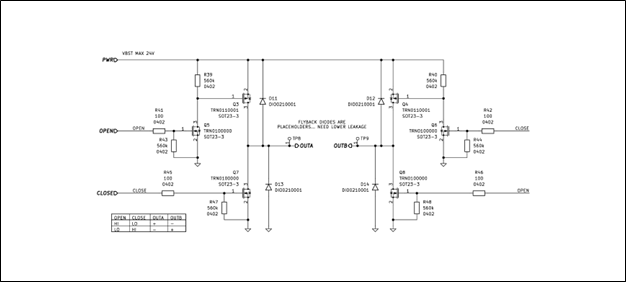
H-Bridge – This circuit is fairly generic. The only slight deviation from a jellybean H-bridge is the addition of Q6 and Q5 which allows me to control all 4 driver FETs with two signals, OPEN and CLOSE. I still need to fine tune my component selection to reduce the leakage presented to the PWR input.
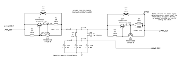
Pulse Storage – This is another energy storage circuit (not the LIPO battery!!) which provides the 50ms (typ) pulse of current required to toggle a latching solenoid. The schematic shows two active current limiting circuits. Capacitor charge current is limited by Q11/Q9, and capacitor discharge current is defined by Q10/Q12. Charge current will be configured to align with the capabilities of the boost converter, and the discharge current will need to be configured for the selected solenoid.
Anyways… that’s the circuit and here’s the PCB I developed this weekend. I’m just working on some final cleanup. I also need to add a few extra 0ohm resistors to isolate each circuit block. Jumpers are great for debugging and general V&V work for an early design.
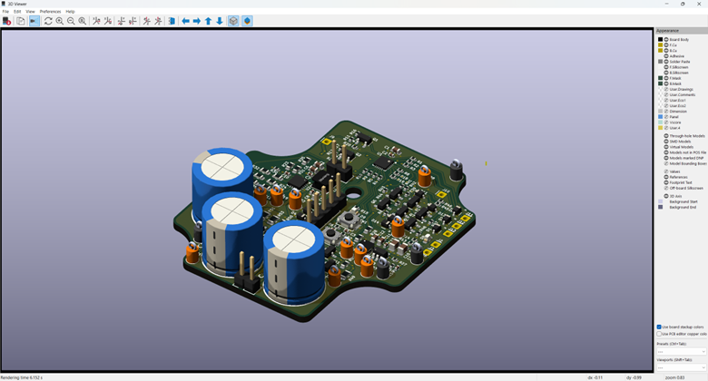
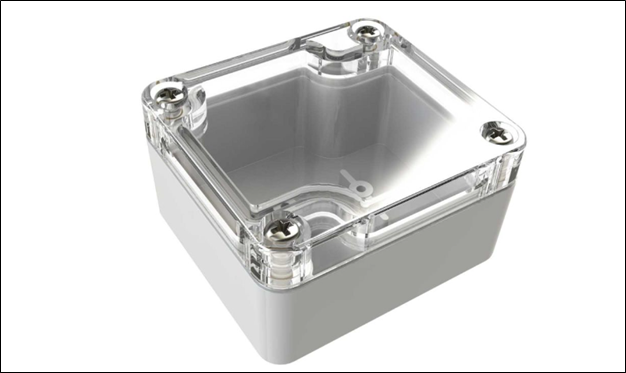
One last thing… If you’re wondering why I set the board outline above, plan to assemble the project in this enclosure from polycase (https://www.polycase.com/wc-20). The LIPO battery is harvested from an old “disposable” vape. My current plan is to rest it ontop of the northern end of the PCB (TPs will need to be removed later). I still am somewhat debating using a LIC instead of a LIPO, but for now I’m prototyping with a LIPO.
Discussions
Become a Hackaday.io Member
Create an account to leave a comment. Already have an account? Log In.