 Jesse Farrell
I was bad and didn’t push my test results. Yikes…. Doing this retroactively now.
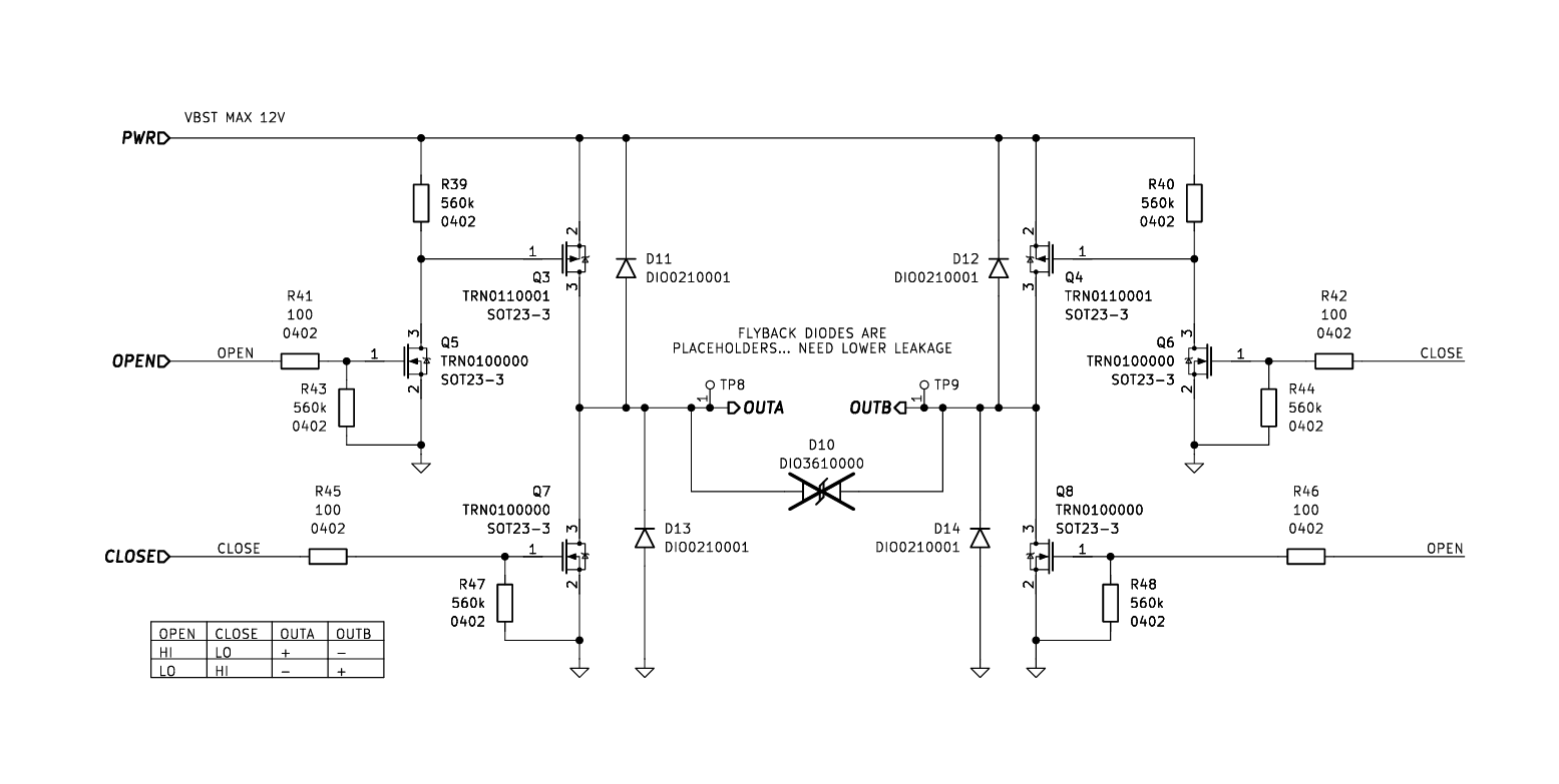
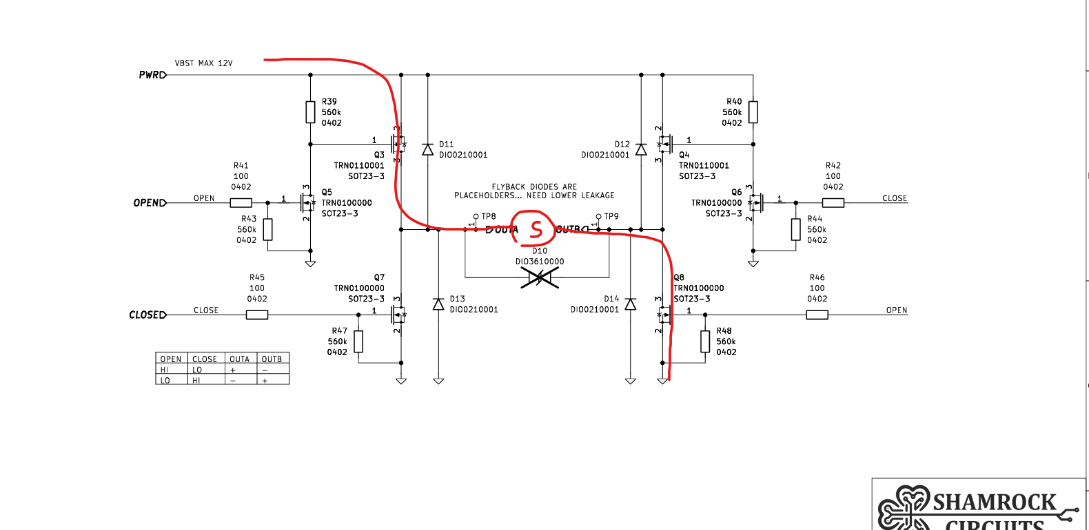
With the REV00 boards in hand, it was time to move on to hardware validation. I had a slew of tests I wanted to run, but at the top of that list was testing the new pulse generation circuit. This includes the bulk cap energy storage, H-bridge, and output current limiter.
The primary goal for this testing was to verify the circuit design and add any findings to the errata. So long as the solenoid toggles properly, I’d consider it a PASS.
Pulse Generation & Initial Logic
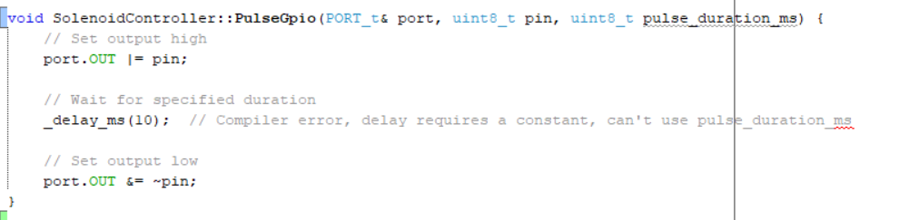
First, I needed to write some firmware for toggling the H-bridge. At this point, I had already developed some code for an ATtiny dev board, so this was a pretty quick task. For early testing, I’m just using a dumb delay; in the future, this will be replaced with a proper sleep method.
Initial No-Load Observations
During this test, I had the bulk caps powered continuously from the boost converter. Findings below.
- Slow Turn-off: There was a noticeable lag in the turn-off time. This was expected given the high-value pull-up resistors on the Q4/Q3 gates. I suspect adding a real load will "clean" this up by providing a discharge path.
- Sloppy Timing: I set a 10ms pulse in code, but the scope showed a much shorter duration. It seems
_delay_ms()is significantly off on this implementation. Since I'm moving away from this for later revisions, I'm not going to lose sleep (😉) over it yet.
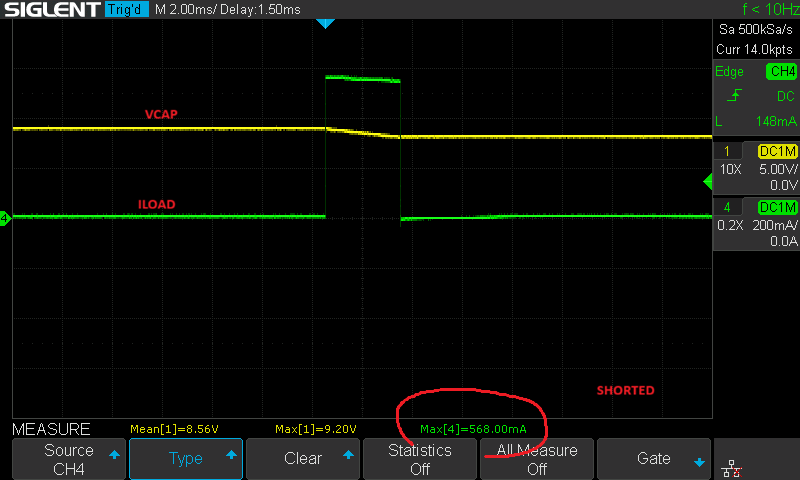
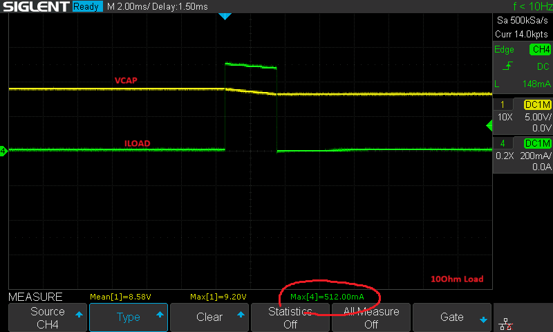
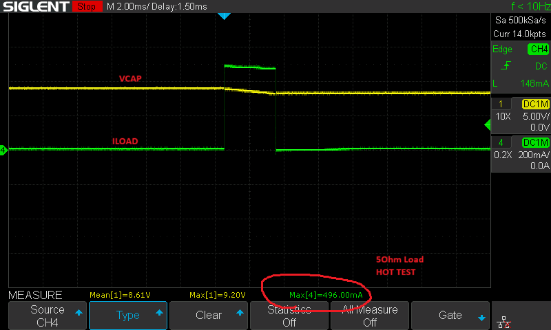
Current Limiter Stress Test
Before connecting the solenoid, I wanted to see if my current limiting circuit could actually limit properly. I used a current sense amplifier and a variable load across OUTA/OUTB. During this test, the boost converter was continuously enabled.
| Load Resistor [Ω] | Peak Current [mA] |
|---|---|
| 10Ω | 512mA |
| 5Ω | 552mA |
| SHORT | 568mA |
Temperature Influence
Since this current limiter relies on the Vbe of Q12, I was curious how bad its thermal influence would be. For a quick sanity check, I held a soldering iron set to 750°F (400°C) about 1cm away from Q12, then nearly touching the transistor's SOT-23 package.
- At 1cm: No measurable difference.
- Nearly Touching: The limit dropped by about 50mA.
The expected temperature coefficient for Vbe is around -2mV/°C. In this system, that translates to:
-2mV / 1.35Ω ≈ -1.48mA/°C
Based on the 50mA drop, I only actually increased the die temperature by ~33°C. I suspect the PCB was pulling heat away from the chip better than I originally anticipated (still 33'C seems low). I’ll likely need to revisit this and saturate the whole system at Tamb in the future.
Driving the Rain Bird Solenoid
Now for the real test: the Rain Bird TBOSPSOL 9V latching solenoid.
Initially, neither the positive nor negative pulses would engage the solenoid. The current limiter (set to 500mA) was working exactly as designed (which was the problem). After checking the coil resistance, I realized it's only 4.7 ohms. At 9V, that’s a theoretical draw of 1.91A! My 500mA ceiling was starving the actuator before it could flip.
To get around this, I shorted R50 with tweezers to bypass the limiter. Afterwards, both positive and negative pulses worked perfectly. I’ll be removing this output current limiter in REV01.
Waveform Breakdown (The "Positive Pulse") Current Limiter Removed
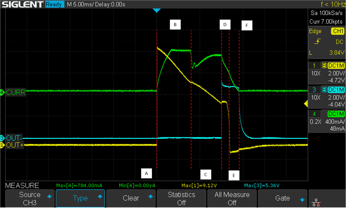
Analyzing the switching cycle reveals some interesting physics in the H-bridge:
- Step A: Idle/Normal operation.
- Step B: Voltage applied. Current ramps up following the inductor current formula. Note: my current sense amplifier is clipping the waveform here.
- Step C: The "Trip": The current hits the threshold where the solenoid physically moves, momentarily changing the effective impedance of the coil.
- Step D: Both OUTA/B go high, suggesting the H-bridge has been disabled. Note that when OPEN goes low, it switches Q8 faster than Q3 because Q3 relies on the pull-up R39. The bridge disables in two steps.
- Step E: Q3 finally turns off. In both Step D and E, the current takes the recirculating path shown below.
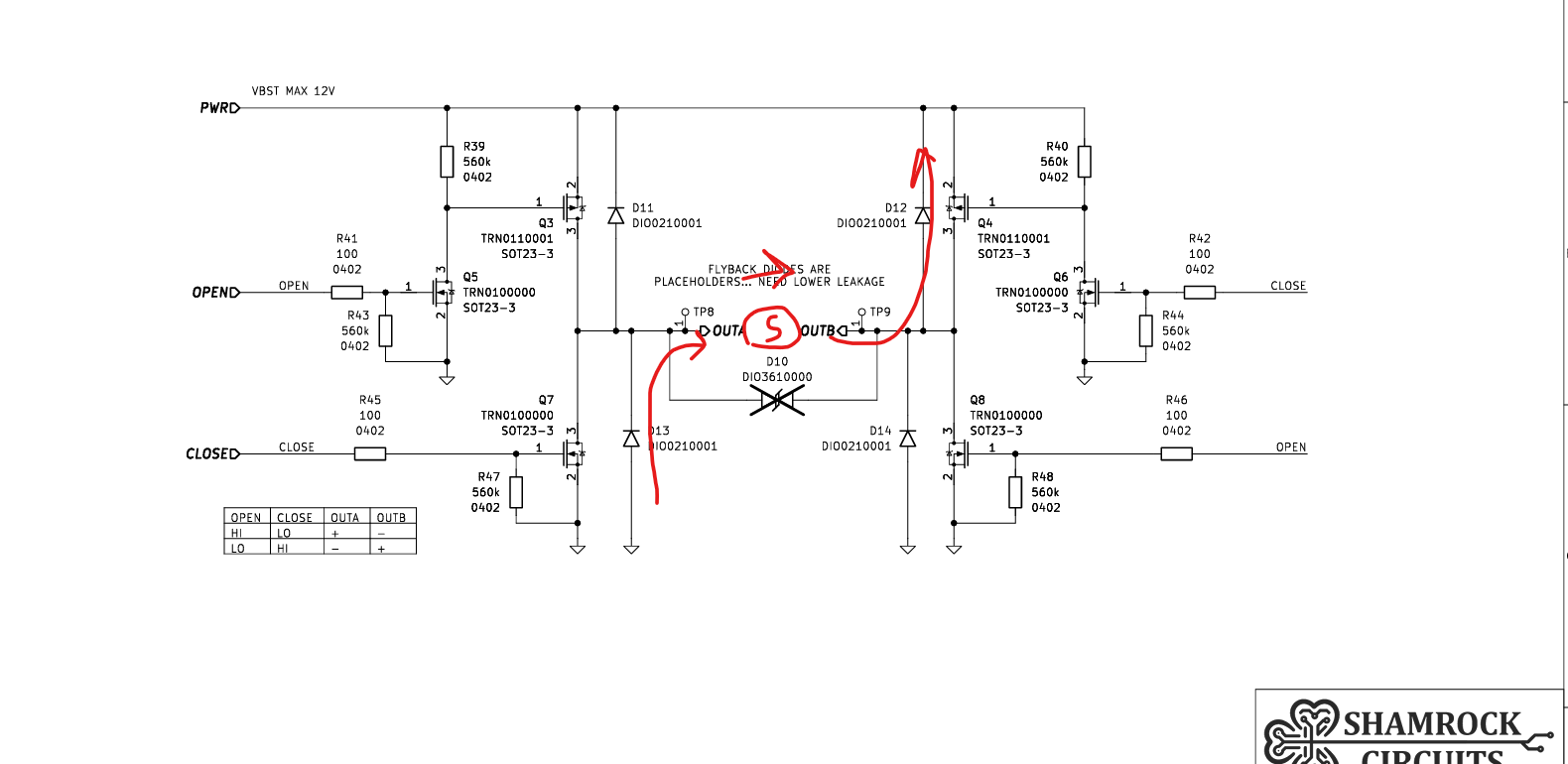
- Step F: Magnetic field energy is depleted. Current hits zero; system returns to steady state.
Final Result
Things look good. The only significant change for REV01 is scrapping the output current limiter. On the current REV00. I included an optional bypass resistor, so testing can continue by adding a jumper resistor. I also should revisit the temperature influence of the current limiter circuit. My results here seem better than I anticipated.
Discussions
Become a Hackaday.io Member
Create an account to leave a comment. Already have an account? Log In.